28.5.4.2 FAC functional description
The access control functionality is implemented in 2 separate blocks within the SoC. The
Flash Management Unit (FMU) includes non-volatile configuration information that is
retrieved during reset and and sent to the platform to control access to the flash array
during normal operation.
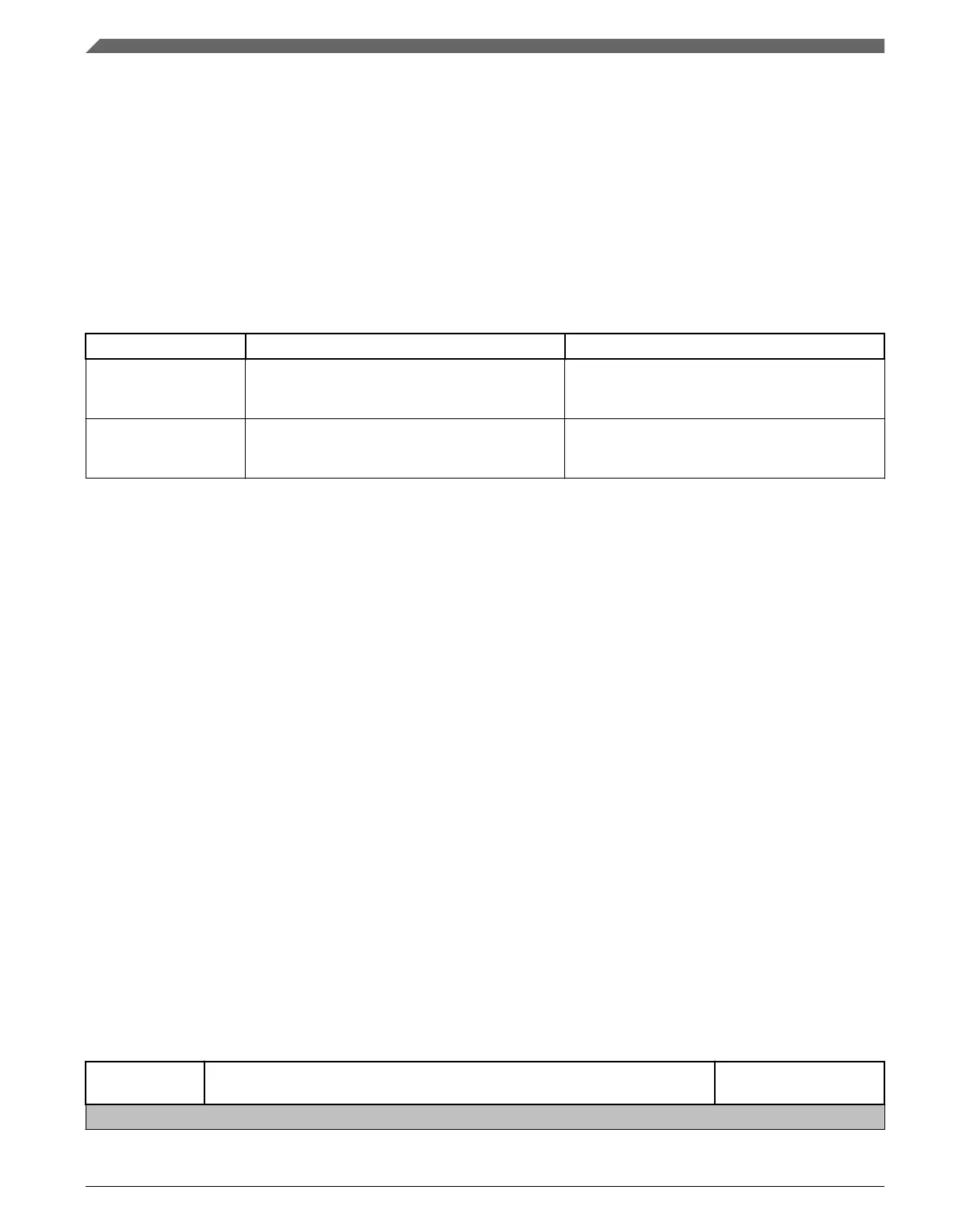
There are (4) 64-bit NVM storage locations to support access control features. These
NVM locations are summarized in the table below.
Table 28-3. NVM Locations
NVM location Description
NVSACC1, NVSACC2 Two locations are ANDed together and loaded
during reset into the x_SACC register to provide
access configuration.
Segment-wise control for supervisor-only access
vs. supervisor and user access
NVXACC1, NVXACC2 Two locations are ANDed together and loaded
during reset into the x_XACC register to provide
access configuration.
Segment-wise control for execute-only vs. data
and execute
Each of these NVM locations is programmable through a Program Once flash command
and can be programmed one time. These NVM locations are unaffected by Erase All
Blocks flash command and debug interface initiated mass erase operations. Since the 2
NVXACCx fields are ANDed, the access protection can only be increased. A segment's
access controls can be changed from data read and execute (XAn =1) to execute-only
(XAn =0), or from supervisor and user mode (SAn = 1) to supervisor-only mode (SAn =
0).
The flash is released from reset early while the core continues to be held in reset. The
FMU captures the NVM access control information in internal registers. The FMU ANDs
the multiple execute-only fields to create a single execute-only field. This execute-only
field driven to the platform is static prior to the core being released from reset. The
supervisor-only field is handled in the same manner.
The FMU includes the FAC registers that provide control access to the flash address
space. During the address phase of every attempted flash transfer, the supervisor access
(SAn) and execute access (XAn) bits are examined to either allow or deny access. If
access is denied, then the access is aborted and terminates with a bus error; the read data
is also zeroed.
The next table shows segment assignments relative to the flash location.
Table 28-4. Flash Protection Ranges
SAn and XAn
Bit
Protected Segment Address Range Segment Size (Fraction
of total Flash)
64 Segment Encodings
Table continues on the next page...
Functional description
K22F Sub-Family Reference Manual, Rev. 4, 08/2016
622 NXP Semiconductors

 Loading...