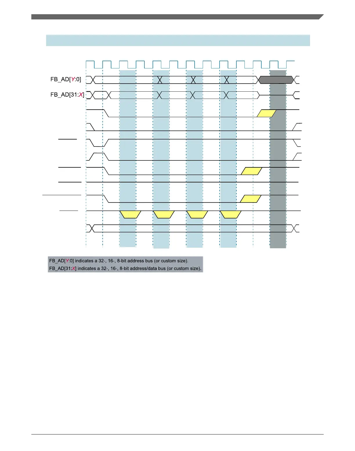
32-bit Write Burst to 8-bit port 3-2-2-2, with 1 wait state
Wait StateWait StateWait State
Address
Address
DataData Data
Add+1 Add+2
Add+3
Data
FB_CLK
TSIZ = 00
AA=1
AA=0
FB_RW
FB_TS
FB_ALE
FB_TBST
FB_OEn
FB_BE/BWEn
FB_TA
FB_TSIZ[1:0]
AA=1
AA=0
FB_CSn
S0 WS S2 S2S2S1
WS/SWS
S2 S3 S4
Wait State
WS/SWS
WS/SWS
S0
Dead State
AA=1
AA=0
S0 WS S2 S2S2S1
WS/SWS
S2 S3 S4
WS/SWS
WS/SWS
S0
AA=0
WS=Wait State SWS=Secondary Wait State
AA=1
AA=0
Write32bBurst1WS.svg
Figure 31-26. 32-bit-write burst to 8-bit port 3-2-2-2 (one wait state)
31.4.12.9
32-bit-read burst from 8-bit port 3-1-1-1 (address setup and
hold)
If address setup and hold are used, only the first and last beat of the burst cycle are
affected. The following figure shows a read cycle with one clock of address setup and
address hold.
Note
In non-multiplexed address/data mode, the address on FB_A
increments only during internally-terminated burst cycles
(CSCRn[AA] = 1b). The attached device must be able to
Chapter 31 External Bus Interface (FlexBus)
K22F Sub-Family Reference Manual, Rev. 4, 08/2016
NXP Semiconductors 735

 Loading...