If the bus frequency is less than f
ADCK
, precise sample time for continuous conversions
cannot be guaranteed when short sample is enabled, that is, when CFG1[ADLSMP]=0.
The maximum total conversion time is determined by the clock source chosen and the
divide ratio selected. The clock source is selectable by CFG1[ADICLK], and the divide
ratio is specified by CFG1[ADIV].
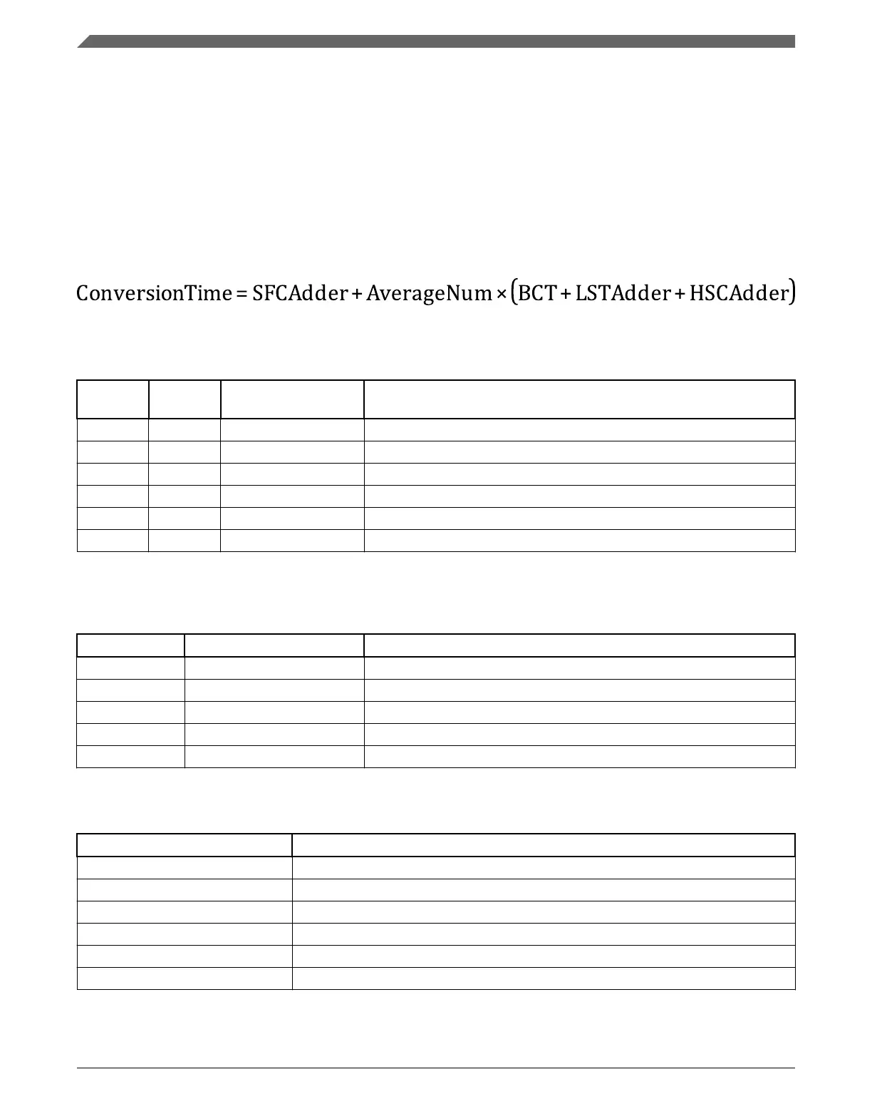
The maximum total conversion time for all configurations is summarized in the equation
below. See the following tables for the variables referenced in the equation.
Equation 1. Conversion time equation
Table 34-3. Single or first continuous time adder (SFCAdder)
CFG1[AD
LSMP]
CFG2[AD
ACKEN]
CFG1[ADICLK] Single or first continuous time adder (SFCAdder)
1 x 0x, 10 3 ADCK cycles + 5 bus clock cycles
1 1 11 3 ADCK cycles + 5 bus clock cycles
1
1 0 11 5 μs + 3 ADCK cycles + 5 bus clock cycles
0 x 0x, 10 5 ADCK cycles + 5 bus clock cycles
0 1 11 5 ADCK cycles + 5 bus clock cycles
1
0 0 11 5 μs + 5 ADCK cycles + 5 bus clock cycles
1. To achieve this time, CFG2[ADACKEN] must be 1 for at least 5 μs prior to the conversion is initiated.
Table 34-4. Average number factor (AverageNum)
SC3[AVGE] SC3[AVGS] Average number factor (AverageNum)
0 xx 1
1 00 4
1 01 8
1 10 16
1 11 32
Table 34-5. Base conversion time (BCT)
Mode Base conversion time (BCT)
8b single-ended 17 ADCK cycles
9b differential 27 ADCK cycles
10b single-ended 20 ADCK cycles
11b differential 30 ADCK cycles
12b single-ended 20 ADCK cycles
13b differential 30 ADCK cycles
Table continues on the next page...
Functional description
K22F Sub-Family Reference Manual, Rev. 4, 08/2016
796 NXP Semiconductors

 Loading...