legacy
PWM synchronization
end
= 0
enhanced PWM synchronization
begin
= 1
SYNCMODE
bit ?
= 0
end
end
end
end
end
= 1
= 1
0 =
= 1
= 0
= 1
0 =
= 1
= 1
= 1
= 0
= 0
= 0
MOD register is
updated by software trigger
MOD register is
updated by hardware trigger
software
trigger
hardware
trigger
FTM counter is reset by
software trigger
FTM counter is reset by
hardware trigger
SWWRBUF
bit ?
HWWRBUF
bit ?
SWSYNC
bit ?
SWRSTCNT
bit ?
wait the next selected
loading point
update MOD with
its buffer value
clear SWSYNC bit
clear SWSYNC bit
update MOD with
its buffer value
TRIGn
bit ?
wait hardware trigger n
HWTRIGMODE
bit ?
clear TRIGn bit
wait the next selected
loading point
update MOD with
its buffer value
update MOD with
its buffer value
HWRSTCNT
bit ?
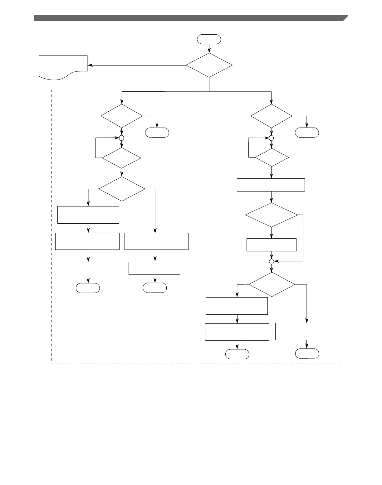
Figure 39-46. MOD register synchronization flowchart
In the case of legacy PWM synchronization, the MOD register synchronization depends
on PWMSYNC and REINIT bits according to the following description.
If (SYNCMODE = 0), (PWMSYNC = 0), and (REINIT = 0), then this synchronization is
made on the next selected loading point after an enabled trigger event takes place. If the
trigger event was a software trigger, then the SWSYNC bit is cleared on the next selected
Chapter 39 FlexTimer Module (FTM)
K22F Sub-Family Reference Manual, Rev. 4, 08/2016
NXP Semiconductors 977

 Loading...