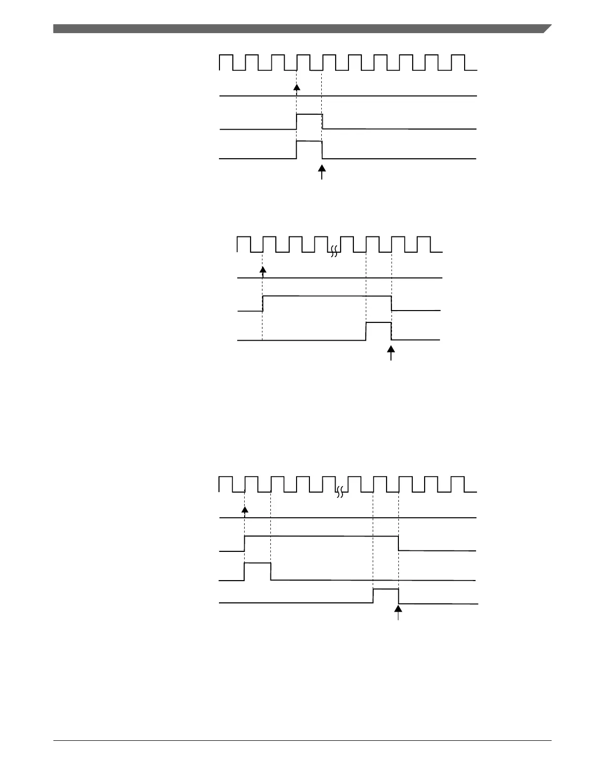
system clock
MOD register is updated
write 1 to SWSYNC bit
SWSYNC bit
software trigger event
Figure 39-49. MOD synchronization with (SYNCMODE = 0), (PWMSYNC = 0), (REINIT =
1), and software trigger was used
system clock
MOD register is updated
write 1 to TRIG0 bit
TRIG0 bit
trigger 0 event
Figure 39-50. MOD synchronization with (SYNCMODE = 0), (HWTRIGMODE = 0),
(PWMSYNC = 0), (REINIT = 1), and a hardware trigger was used
If (SYNCMODE = 0) and (PWMSYNC = 1), then this synchronization is made on the
next selected loading point after the software trigger event takes place. The SWSYNC bit
is cleared on the next selected loading point:
system clock
selected loading point
MOD register is updated
write 1 to SWSYNC bit
SWSYNC bit
software trigger event
Figure 39-51. MOD synchronization with (SYNCMODE = 0) and (PWMSYNC = 1)
Chapter 39 FlexTimer Module (FTM)
K22F Sub-Family Reference Manual, Rev. 4, 08/2016
NXP Semiconductors 979

 Loading...