end
= 0
update OUTMASK register at
each rising edge of system clock
begin
software
trigger
endend
end
end
= 0
= 0
= 1
= 1
= 1
= 1
= 0
= 1
0 =
0 =
1 =
1 =
0 =
legacy
PWM synchronization
SYNCHOM
bit ?
update OUTMASK register by
PWM synchronization
update OUTMASK
with its buffer value
SYNCMODE
bit ?
clear TRIGn bit
HWTRIGMODE
bit ?
update OUTMASK
with its buffer value
wait hardware trigger n
TRIGn
bit ?
HWOM
bit ?
SWOM
bit ?
SWSYNC
bit ?
rising edge
of system
clock ?
update OUTMASK
with its buffer value
hardware
trigger
OUTMASK is updated
by software trigger
OUTMASK is updated
by hardware trigger
enhanced PWM synchronization
= yes
no =
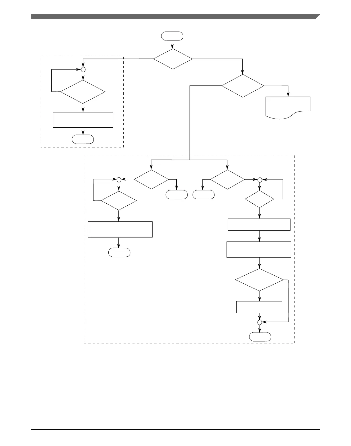
Figure 39-52. OUTMASK register synchronization flowchart
In the case of legacy PWM synchronization, the OUTMASK register synchronization
depends on PWMSYNC bit according to the following description.
Chapter 39 FlexTimer Module (FTM)
K22F Sub-Family Reference Manual, Rev. 4, 08/2016
NXP Semiconductors 981

 Loading...