when the channel (n+1) match (FTM counter = C(n+1)V) occurs, the channel (n+1)
output remains at the high value until the end of the deadtime delay when the channel (n
+1) output is cleared.
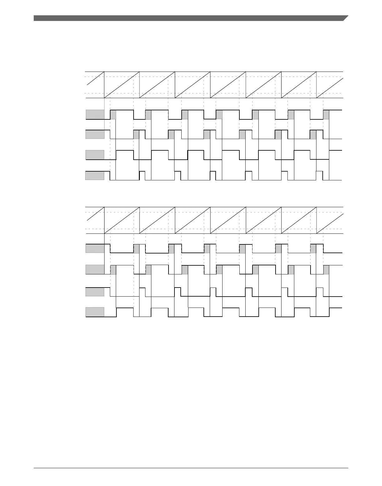
FTM counter
channel (n+1) match
channel (n) match
channel (n) output
(before deadtime
insertion)
channel (n+1) output
(before deadtime
insertion)
channel (n) output
(after deadtime
insertion)
channel (n+1) output
(after deadtime
insertion)
Figure 39-66. Deadtime insertion with ELSnB:ELSnA = 1:0, POL(n) = 0, and POL(n+1) = 0
FTM counter
channel (n+1) match
channel (n) output
(before deadtime
insertion)
channel (n+1) output
(before deadtime
insertion)
channel (n) output
(after deadtime
insertion)
channel (n+1) output
(after deadtime
insertion)
channel (n) match
Figure 39-67. Deadtime insertion with ELSnB:ELSnA = X:1, POL(n) = 0, and POL(n+1) = 0
NOTE
• The deadtime feature must be used only in Complementary
mode.
• The deadtime feature is not available in Output Compare
mode.
39.4.14.1
Deadtime insertion corner cases
If (PS[2:0] is cleared), (DTPS[1:0] = 0:0 or DTPS[1:0] = 0:1):
Chapter 39 FlexTimer Module (FTM)
K22F Sub-Family Reference Manual, Rev. 4, 08/2016
NXP Semiconductors 993

 Loading...