• and the deadtime delay is greater than or equal to the channel (n) duty cycle ((C(n
+1)V – C(n)V) × system clock), then the channel (n) output is always the inactive
value (POL(n) bit value).
• and the deadtime delay is greater than or equal to the channel (n+1) duty cycle
((MOD – CNTIN + 1 – (C(n+1)V – C(n)V) ) × system clock), then the channel (n+1)
output is always the inactive value (POL(n+1) bit value).
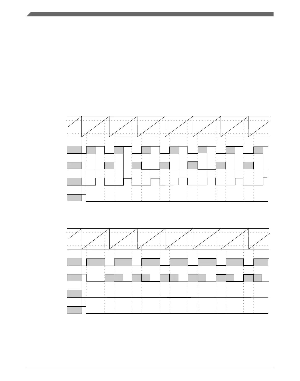
Although, in most cases the deadtime delay is not comparable to channels (n) and (n+1)
duty cycle, the following figures show examples where the deadtime delay is comparable
to the duty cycle.
FTM counter
channel (n+1) match
channel (n) match
channel (n) output
(before deadtime
insertion)
channel (n) output
(after deadtime
insertion)
channel (n+1) output
(before deadtime
insertion)
channel (n+1) output
(after deadtime
insertion)
Figure 39-68. Example of the deadtime insertion (ELSnB:ELSnA = 1:0, POL(n) = 0, and
POL(n+1) = 0) when the deadtime delay is comparable to channel (n+1) duty cycle
FTM counter
channel (n+1) match
channel (n) match
channel (n) output
(before deadtime
insertion)
channel (n) output
(after deadtime
insertion)
channel (n+1) output
(before deadtime
insertion)
channel (n+1) output
(after deadtime
insertion)
Figure 39-69. Example of the deadtime insertion (ELSnB:ELSnA = 1:0, POL(n) = 0, and
POL(n+1) = 0) when the deadtime delay is comparable to channels (n) and (n+1) duty
cycle
Functional description
K22F Sub-Family Reference Manual, Rev. 4, 08/2016
994 NXP Semiconductors

 Loading...