If the fault control and fault input n are enabled and a rising edge at the fault input n
signal is detected, a fault condition has occurred and the FAULTFn bit is set. The
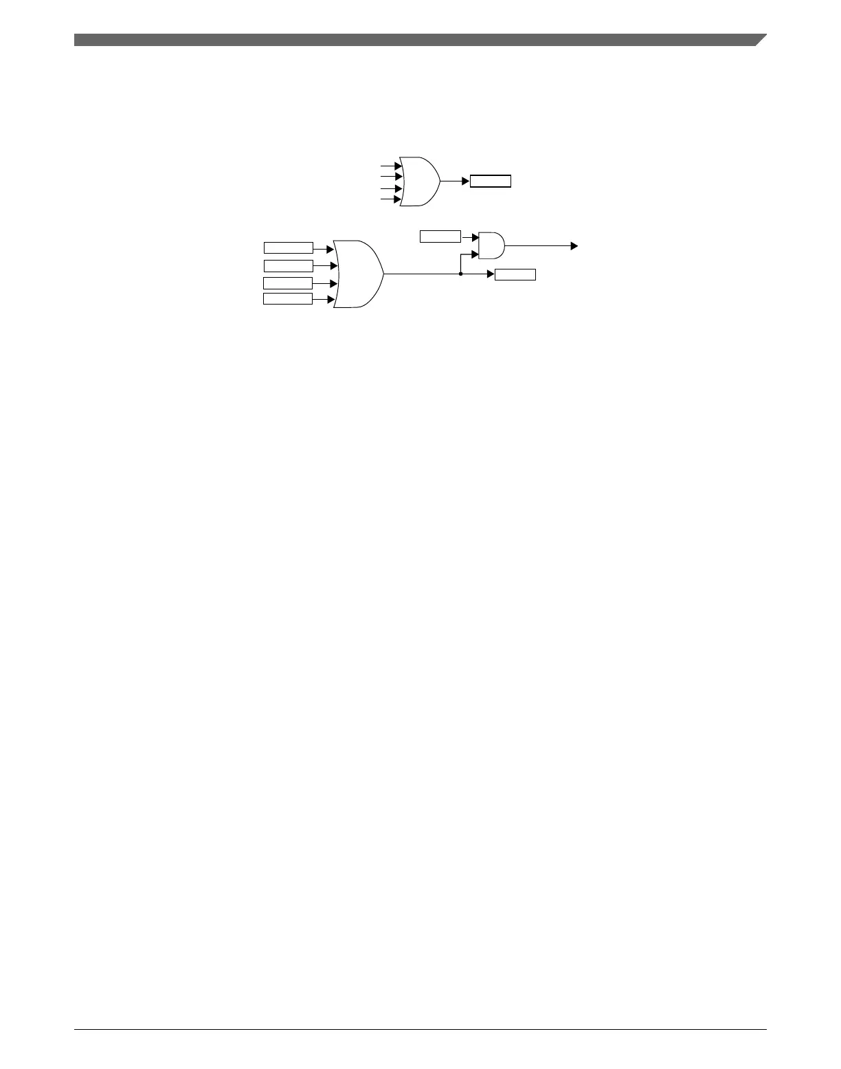
FAULTF bit is the logic OR of FAULTFn[3:0] bits. See the following figure.
fault interrupt
FAULTIE
FAULTIN
fault input 0 value
fault input 1 value
fault input 2 value
fault input 3 value
FAULTF
FAULTF0
FAULTF1
FAULTF2
FAULTF3
Figure 39-72. FAULTF and FAULTIN bits and fault interrupt
If the fault control is enabled (FAULTM[1:0] ≠ 0:0), a fault condition has occurred and
(FAULTEN = 1), then outputs are forced to their safe values:
• Channel (n) output takes the value of POL(n)
• Channel (n+1) takes the value of POL(n+1)
The fault interrupt is generated when (FAULTF = 1) and (FAULTIE = 1). This interrupt
request remains set until:
• Software clears the FAULTF bit by reading FAULTF bit as 1 and writing 0 to it
• Software clears the FAULTIE bit
• A reset occurs
39.4.16.1
Automatic fault clearing
If the automatic fault clearing is selected (FAULTM[1:0] = 1:1), then the channels output
disabled by fault control is again enabled when the fault input signal (FAULTIN) returns
to zero and a new PWM cycle begins. See the following figure.
Chapter 39 FlexTimer Module (FTM)
K22F Sub-Family Reference Manual, Rev. 4, 08/2016
NXP Semiconductors 997

 Loading...