UM10360 All information provided in this document is subject to legal disclaimers. © NXP B.V. 2013. All rights reserved.
User manual Rev. 3 — 19 December 2013 289 of 841
NXP Semiconductors
UM10360
Chapter 13: LPC176x/5x USB OTG
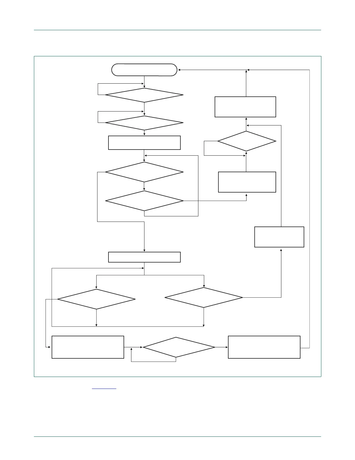
Figure 41 shows the actions that the OTG software stack should take in response to the
hardware actions setting REMOVE_PU, HNP_SUCCESS, AND HNP_FAILURE. The
relationship of the software actions to the Dual-Role B-Device states is also shown.
B-device states are in bold font with a circle around them.
Fig 40. Hardware support for B-device switching from peripheral state to host state
idle
set HNP_SUCCESS
set PORT_FUNC[0]
drive J on internal host controller port
and SE0 on U1
wait 25 s for bus to settle
disconnect device controller from U1
set REMOVE_PU
bus suspended ?
set HNP_FAILURE,
clear B_HNP_TRACK,
clear PU_REMOVED
reconnect port U1 to the
device controller
reconnect port U1 to the
device controller
connect U1 to host controller
clear B_HNP_TRACK
clear PU_REMOVED
PU_REMOVED set?
PU_REMOVED set?
bus reset/resume detected?
connect from A-device detected?
bus reset/resume detected?
SE0 sent by host?
B_HNP_TRACK = 0
no
yes
yes
no
no
yes
yes
no
B_HNP_TRACK = 1 ?
no
no
no
yes

 Loading...


