UM10360 All information provided in this document is subject to legal disclaimers. © NXP B.V. 2013. All rights reserved.
User manual Rev. 3 — 19 December 2013 293 of 841
NXP Semiconductors
UM10360
Chapter 13: LPC176x/5x USB OTG
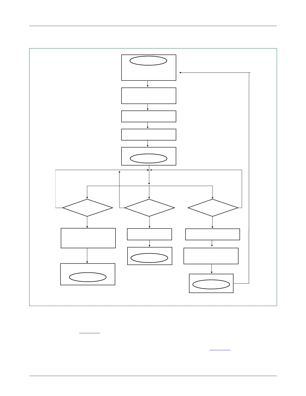
Note that only the subset of A-device HNP states and state transitions supported by
hardware are shown. Software is responsible for implementing all of the HNP states.
Figure 43
may appear to imply that the interrupt bits such as TMR should be polled, but
this is not necessary if the corresponding interrupt is enabled.
Following are code examples that show how the actions in Figure 43
are accomplished.
The examples assume that ISP1302 is being used as the external OTG transceiver.
Set BDIS_ACON_EN in external OTG transceiver
Fig 43. State transitions implemented in software during A-device switching from host to peripheral
HNP_SUCCESS set?
HNP_FAILURE set?TMR set?
a_host
when host sends SET_FEATURE
with a_hnp_enable,
set A_HNP_TRACK
stop the OTG timer
a_suspend
a_host
a_wait_vfall
go to
a_peripheral
go to
go to
yes yes
yes
set BDIS_ACON_EN
in external OTG transceiver
load and enable OTG timer
clear BDIS_ACON_EN
bit in external OTG transceiver
clear BDIS_ACON_EN
bit in external OTG transceiver
discharge V
BUS
stop OTG timer
suspend host on port 1
go to
no
no
no

 Loading...


