UM10360 All information provided in this document is subject to legal disclaimers. © NXP B.V. 2013. All rights reserved.
User manual Rev. 3 — 19 December 2013 33 of 841
NXP Semiconductors
UM10360
Chapter 4: LPC176x/5x Clocking and power control
Since chip operation always begins using the Internal RC Oscillator, and the main
oscillator may not be used at all in some applications, it will only be started by software
request. This is accomplished by setting the OSCEN bit in the SCS register, as described
in Table 13
. The main oscillator provides a status flag (the OSCSTAT bit in the SCS
register) so that software can determine when the oscillator is running and stable. At that
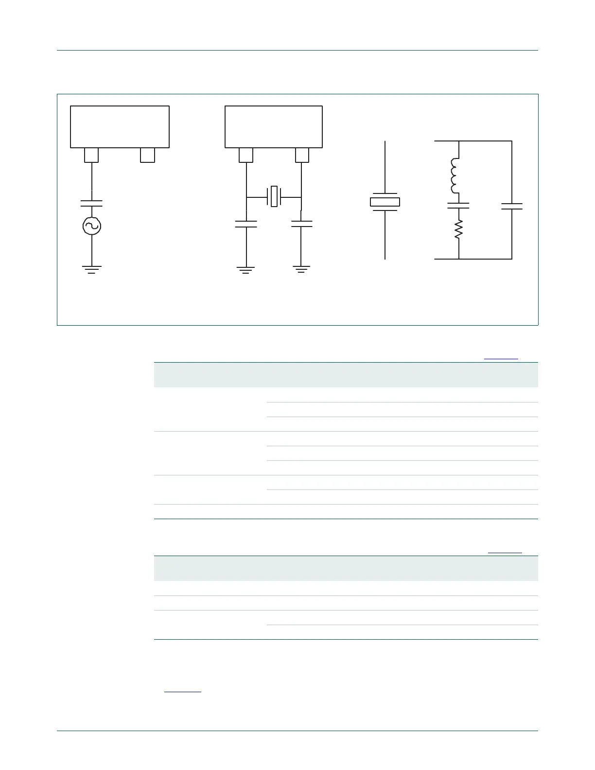
Fig 8. Oscillator modes and models: a) slave mode of operation, b) oscillation mode of operation, c) external
crystal model used for C
X1
/
X2
evaluation
LPC17xx LPC17xx
Clock
C
C
C
X1
C
X2
C
L
C
P
L
R
S
< = >
a) b) c)
Xtal
XTAL1 XTAL2
XTAL1 XTAL2
Table 15. Recommended values for C
X1/X2
in oscillation mode (crystal and external
components parameters) low frequency mode (OSCRANGE = 0, see Table 13)
Fundamental oscillation
frequency F
OSC
Crystal load
capacitance C
L
Maximum crystal
series resistance R
S
External load
capacitors C
X1
, C
X2
1 MHz to 5 MHz 10 pF < 300 18 pF, 18 pF
20 pF < 300
39 pF, 39 pF
30 pF < 300
57 pF, 57 pF
5 MHz to 10 MHz 10 pF < 300
18 pF, 18 pF
20 pF < 200
39 pF, 39 pF
30 pF < 100
57 pF, 57 pF
10 MHz to 15 MHz 10 pF < 160
18 pF, 18 pF
20 pF < 60
39 pF, 39 pF
15 MHz to 20 MHz 10 pF < 80
18 pF, 18 pF
Table 16. Recommended values for C
X1/X2
in oscillation mode (crystal and external
components parameters) high frequency mode (OSCRANGE = 1, see Table 13
)
Fundamental oscillation
frequency F
OSC
Crystal load
capacitance C
L
Maximum crystal
series resistance R
S
External load
capacitors C
X1
, C
X2
15 MHz to 20 MHz 10 pF < 180 18 pF, 18 pF
20 pF < 100
39 pF, 39 pF
20 MHz to 25 MHz 10 pF < 160
18 pF, 18 pF
20 pF < 80
39 pF, 39 pF

 Loading...


