RM0444 Rev 5 1199/1390
RM0444 FD controller area network (FDCAN)
1261
36.3 FDCAN functional description
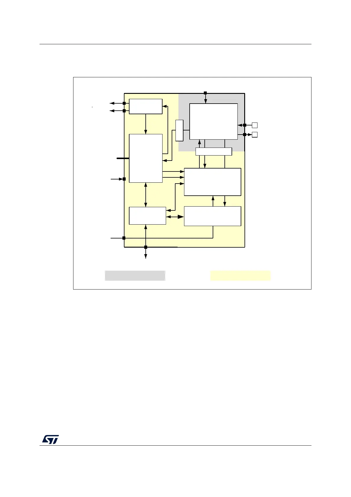
Figure 393. FDCAN block diagram
Dual interrupt lines
The FDCAN peripheral provides two interrupt lines, fdcan_intr0_it and fdcan_intr1_it.
By programming EINT0 and EINT1 bits in FDCAN_ILE register, the interrupt lines can be
separately enabled or disabled.
CAN core
The CAN core contains the Protocol Controller and receive / transmit shift registers. It
handles all ISO 11898-1: 2015 protocol functions and supports both 11-bit and 29-bit
identifiers.
Sync
The Sync block synchronizes signals from the APB clock domain to the CAN kernel clock
domain and vice versa.
MS51819V1
FDCAN_TX
FDCAN_RX
Interrupts
interface
CANFDL
Message RAM
interface
CAN core
fdcan_intr0_it
fdcan_intr1_it
TX Handler
TX prioritization
Frame Synchro
Tx Req
Tx State Rx State
Sync
Sync
fdcan_pclk
Control and
Configuration
registers
RX Handler
Acceptance filter
fdcan_ts[0:15]
Ctrl_APB
fdcan_tq_ck
Kernel clock domain APB clock domain

 Loading...


