RM0444 Rev 5 1209/1390
RM0444 FD controller area network (FDCAN)
1261
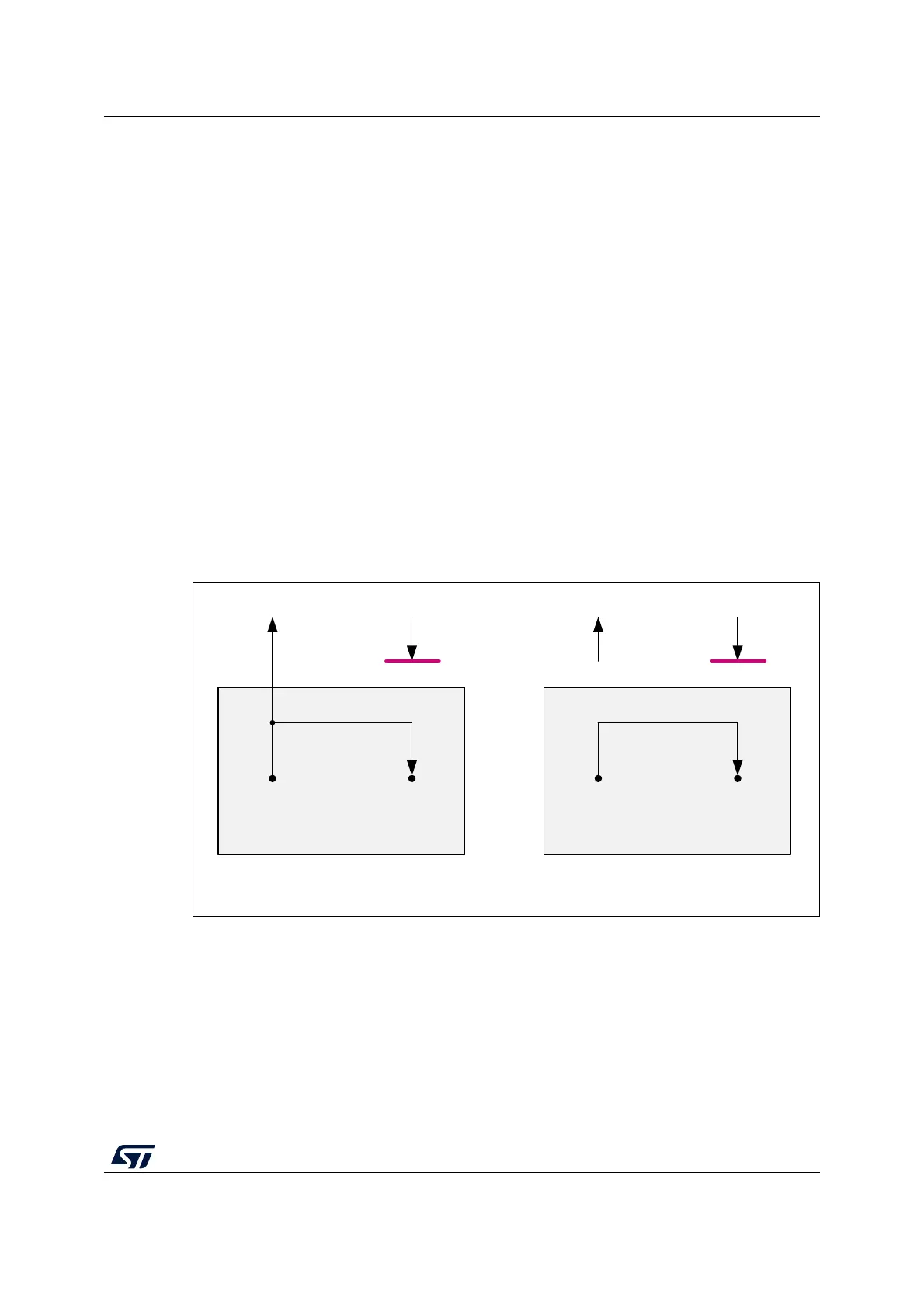
External Loop Back mode
The FDCAN can be set in External Loop Back mode by programming TEST.LBCK to 1. In
Loop Back mode, the FDCAN treats its own transmitted messages as received messages
and stores them (if they pass acceptance filtering) into Rx FIFOs. Figure 397 shows the
connection of transmit and receive signals FDCAN_TX and FDCAN_RX to the FDCAN in
External Loop Back mode.
This mode is provided for hardware self-test. To be independent from external stimulation,
the FDCAN ignores acknowledge errors (recessive bit sampled in the acknowledge slot of a
data / remote frame) in Loop Back mode. In this mode the FDCAN performs an internal
feedback from its transmit output to its receive input. The actual value of the FDCAN_RX
input pin is disregarded by the FDCAN. The transmitted messages can be monitored at the
FDCAN_TX transmit pin.
Internal Loop Back mode
Internal Loop Back mode is entered by programming bits TEST.LBCK and CCCR.MON to 1.
This mode can be used for a “Hot Selftest”, meaning the FDCAN can be tested without
affecting a running CAN system connected to the FDCAN_TX and FDCAN_RX pins. In this
mode, FDCAN_RX pin is disconnected from the FDCAN and FDCAN_TX pin is held
recessive. Figure 397 shows the connection of FDCAN_TX and FDCAN_RX pins to the
FDCAN in case of Internal Loop Back mode.
Figure 397. Pin control in Loop Back mode
Timestamp generation
For timestamp generation the FDCAN supplies a 16-bit wrap-around counter. A prescaler
TSCC.TCP can be configured to clock the counter in multiples of CAN bit times (1 ... 16).
The counter is readable via TSCV[TCV]. A write access to register TSCV resets the counter
to 0. When the timestamp counter wraps around interrupt flag IR[TSW] is set.
On start of frame reception/transmission the counter value is captured and stored into the
timestamp section of a Rx FIFO (RXTS[15:0]) or Tx Event FIFO (TXTS[15:0]) element.
By programming bit TSCC.TSS, a 16-bit timestamp can be used.
FDCAN
MS41463V1
=1
FDCANx_Tx FDCAN_Rx
Tx Rx
Internal Loop Back mode
FDCAN
FDCANx_Tx FDCAN_Rx
Tx Rx
External Loop Back mode

 Loading...


