RM0444 Rev 5 1303/1390
RM0444 Universal serial bus full-speed host/device interface (USB)
1307
the restrictions on the number of available bits, buffer size is represented using the number
of allocated memory blocks, where block size can be selected to choose the trade-off
between fine-granularity/small-buffer and coarse-granularity/large-buffer. The size of
allocated buffer is a part of the endpoint/channel descriptor and it is normally defined during
the enumeration process according to its maxPacketSize parameter value (see “Universal
Serial Bus Specification”).
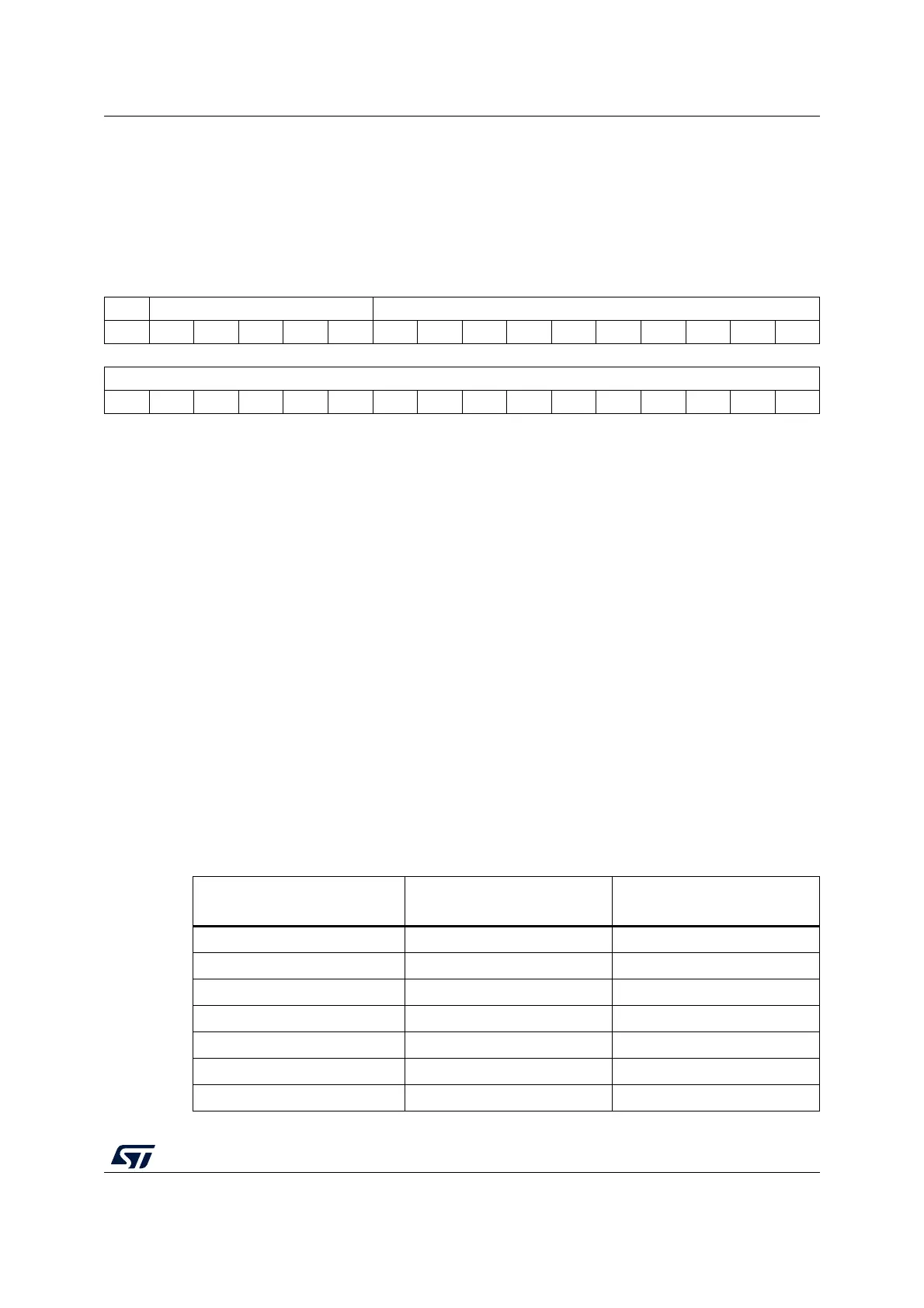
31 30 29 28 27 26 25 24 23 22 21 20 19 18 17 16
BLSIZE NUM_BLOCK[4:0] COUNTn_RX[9:0]
rwrwrwrwrwrwrrrrrrrrrr
1514131211109876543210
ADDRn_RX[15:0]
rw rw rw rw rw rw rw rw rw rw rw rw rw rw rw rw
Bit 31 BLSIZE: Block size
This bit selects the size of memory block used to define the allocated buffer area.
– If BLSIZE = 0, the memory block is 2-byte large, which is the minimum block
allowed in a half-word wide memory. With this block size the allocated buffer size
ranges from 2 to 62 bytes.
– If BLSIZE = 1, the memory block is 32-byte large, which permits to reach the
maximum packet length defined by USB specifications. With this block size the
allocated buffer size theoretically ranges from 32 to 1024 bytes, which is the longest
packet size allowed by USB standard specifications. However, the applicable size is
limited by the available buffer memory.
Bits 30:26 NUM_BLOCK[4:0]: Number of blocks
These bits define the number of memory blocks allocated to this packet buffer. The actual
amount of allocated memory depends on the BLSIZE value as illustrated in Table 228.
Bits 25:16 COUNTn_RX[9:0]: Reception byte count
These bits contain the number of bytes received by the endpoint/channel associated with the
USB_CHEPnR register during the last OUT/SETUP transaction addressed to it.
Bits 15:0 ADDRn_RX[15:0]: Reception buffer address
These bits point to the starting address of the packet buffer, which contains the data received
by the endpoint/channel associated with the USB_CHEPnR register at the next OUT/SETUP
token addressed to it. Bits 1 and 0 must always be written as “00” since packet memory is
word wide and all packet buffers must be word aligned.
Table 228. Definition of allocated buffer memory
Value of
NUM_BLOCK[4:0]
Memory allocated
when BLSIZE=0
Memory allocated
when BLSIZE=1
0 (00000) Not allowed 32 bytes
1 (00001) 2 bytes 64 bytes
2 (00010) 4 bytes 96 bytes
3 (00011) 6 bytes 128 bytes
... ... ...
14 (01110) 28 bytes 480 bytes
15 (01111) 30 bytes

 Loading...


