Power control (PWR) RM0444
140/1390 RM0444 Rev 5
Exiting Standby mode
The MCU exits Standby mode according to section Entering low-power modes. The SBF
status flag in the Power control register 3 (PWR_CR3) indicates that the MCU was in
Standby mode. All registers are reset after wakeup from Standby except for Power control
register 3 (PWR_CR3).
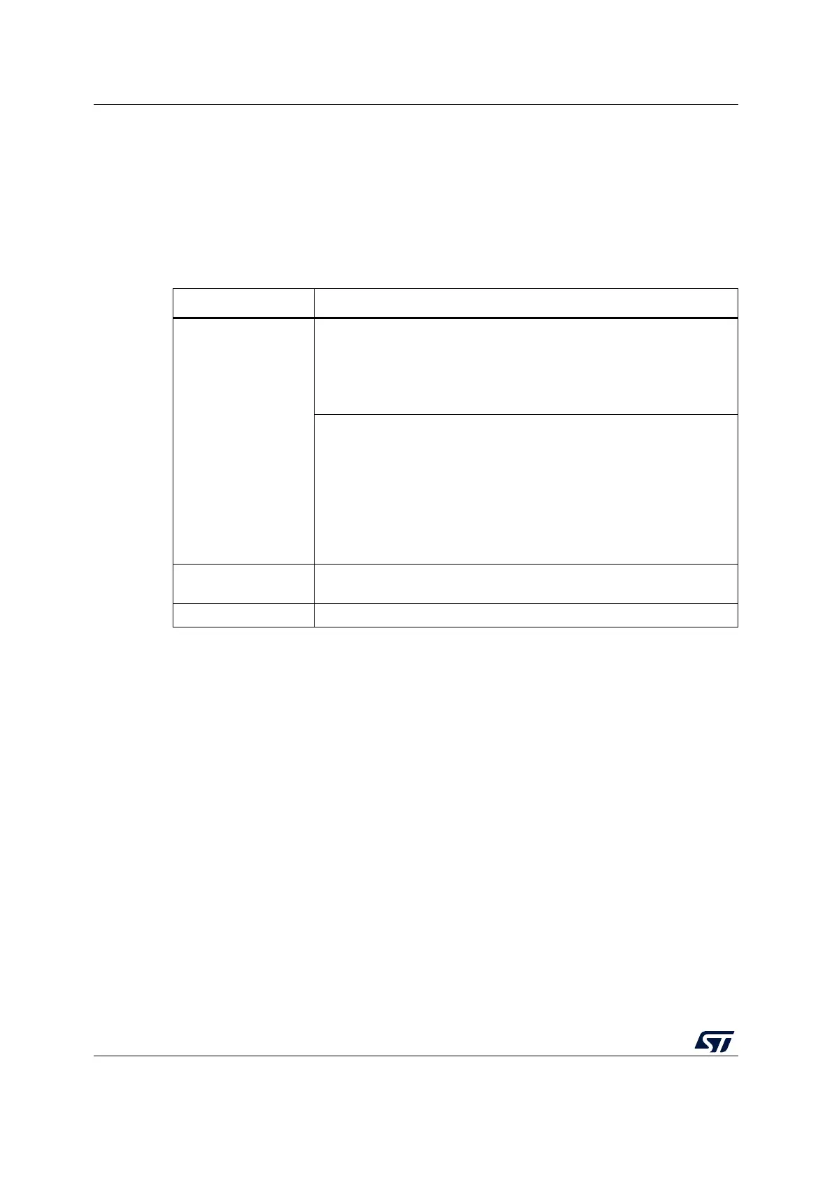
Refer to Table 32: Standby mode summary for more details on how to exit Standby mode.
Table 32. Standby mode summary
Characteristic Description
Mode entry
WFI (Wait for Interrupt) or WFE (Wait for Event) while:
– SLEEPDEEP bit is set in Cortex
®
-M0+ System Control register
– No interrupt (for WFI) or event (for WFE) is pending
– LPMS = “011” in
Power control register 1 (PWR_CR1)
– WUFx bits are cleared in Power status register 1 (PWR_SR1)
On return from ISR while:
– SLEEPDEEP bit is set in Cortex
®
-M0+ System Control register
– SLEEPONEXIT = 1
– No interrupt is pending
– LPMS = “011” in
Power control register 1 (PWR_CR1)
– WUFx bits are cleared in Power status register 1 (PWR_SR1)
– The RTC flag corresponding to the chosen wakeup source (RTC Alarm
A, RTC Alarm B, RTC wakeup, tamper or timestamp flags) is cleared
Mode exit
WKUPx pin edge, RTC event, TAMP event, external reset on NRST pin,
IWDG reset, BOR
Wakeup latency Reset phase

 Loading...


