RM0444 Rev 5 1107/1390
RM0444 Low-power universal asynchronous receiver transmitter (LPUART)
1138
enable bit (EIE bit in the LPUART_CR3 register), which, if set, enables an interrupt after the
current byte if any of these errors occur.
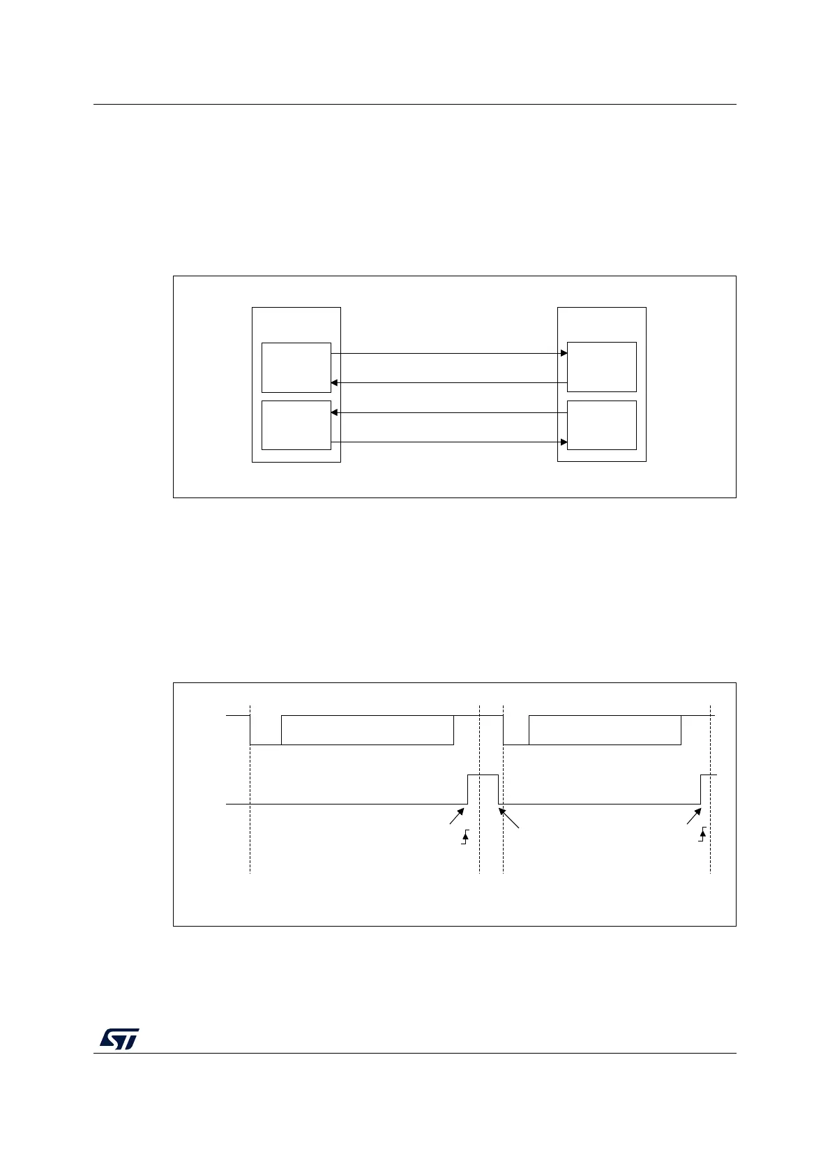
34.4.13 RS232 Hardware flow control and RS485 Driver Enable
It is possible to control the serial data flow between 2 devices by using the nCTS input and
the nRTS output. The Figure 336 shows how to connect 2 devices in this mode:
Figure 350. Hardware flow control between 2 LPUARTs
RS232 RTS and CTS flow control can be enabled independently by writing the RTSE and
CTSE bits respectively to 1 (in the LPUART_CR3 register).
RS232 RTS flow control
If the RTS flow control is enabled (RTSE = 1), then nRTS is asserted (tied low) as long as
the LPUART receiver is ready to receive a new data. When the receive register is full, nRTS
is deasserted, indicating that the transmission is expected to stop at the end of the current
frame. Figure 351 shows an example of communication with RTS flow control enabled.
Figure 351. RS232 RTS flow control
Note: When FIFO mode is enabled, nRTS is deasserted only when RXFIFO is full.
MSv31892V2
TX circuit
LPUART 1
TX
RX circuit
RX circuit
LPUART 2
TX circuit
TX
CTS
CTS
RTS
RX
RTS
RX
MSv31168V1
Start
bit
Start
bit
Stop
bit
Idle
Stop
bit
RX
nRTS
Data 1 read
Data 2 can now be transmitted
RXNE
RXNE
Data 1 Data 2

 Loading...


