RM0444 Rev 5 709/1390
RM0444 Basic timers (TIM6/TIM7)
714
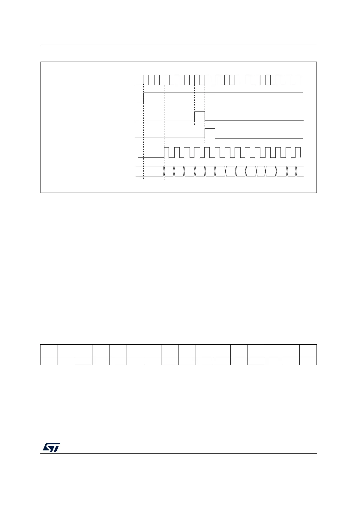
Figure 220. Control circuit in normal mode, internal clock divided by 1
23.3.5 Debug mode
When the microcontroller enters the debug mode (Cortex
®
-M0+ core - halted), the TIMx
counter either continues to work normally or stops, depending on the DBG_TIMx_STOP
configuration bit in the DBG module. For more details, refer to Section 40.9.2: Debug
support for timers, watchdog and I
2
C.
23.4 TIM6/TIM7 registers
Refer to Section 1.2 on page 53 for a list of abbreviations used in register descriptions.
The peripheral registers can be accessed by half-words (16-bit) or words (32-bit).
23.4.1 TIMx control register 1 (TIMx_CR1)(x = 6 to 7)
Address offset: 0x00
Reset value: 0x0000
Internal clock
Counter clock = CK_CNT = CK_PSC
Counter register
CEN=CNT_EN
UG
CNT_INIT
MS31085V2
00
02
03
04 05
06 0732
33
34 35 36
31
01
1514131211109876543210
Res. Res. Res. Res.
UIFRE
MAP
Res. Res. Res. ARPE Res. Res. Res. OPM URS UDIS CEN
rw rw rw rw rw rw
Bits 15:12 Reserved, must be kept at reset value.
Bit 11 UIFREMAP: UIF status bit remapping
0: No remapping. UIF status bit is not copied to TIMx_CNT register bit 31.
1: Remapping enabled. UIF status bit is copied to TIMx_CNT register bit 31.
Bits 10:8 Reserved, must be kept at reset value.

 Loading...


