Digital-to-analog converter (DAC) RM0444
422/1390 RM0444 Rev 5
1. Set the two DAC channel trigger enable bits TEN1 and TEN2
2. Configure the same trigger source for both DAC channels by setting the same value in
the TSEL1 and TSEL2 bitfields.
3. Configure the two DAC channel WAVEx[1:0] bits as 1x and the same maximum
amplitude value using the MAMPx[3:0] bits.
4. Load the dual DAC channel data into the desired DHR register (DAC_DHR12RD,
DAC_DHR12LD or DAC_DHR8RD).
When a trigger arrives, the DAC channel1 triangle counter, with the same triangle
amplitude, is added to the DHR1 register and the sum is transferred into DAC_DOR1 (three
dac_pclk clock cycles later). The DAC channel1 triangle counter is then updated.
At the same time, the DAC channel2 triangle counter, with the same triangle amplitude, is
added to the DHR2 register and the sum is transferred into DAC_DOR2 (three dac_pclk
clock cycles later). The DAC channel2 triangle counter is then updated.
Simultaneous trigger with different triangle generation
To configure the DAC in this conversion mode, the following sequence is required:
1. Set the two DAC channel trigger enable bits TEN1 and TEN2
2. Configure the same trigger source for both DAC channels by setting the same value in
the TSEL1 and TSEL2 bitfields.
3. Configure the two DAC channel WAVEx[1:0] bits as 1x and set different maximum
amplitude values in the MAMP1[3:0] and MAMP2[3:0] bits.
4. Load the dual DAC channel data into the desired DHR register (DAC_DHR12RD,
DAC_DHR12LD or DAC_DHR8RD).
When a trigger arrives, the DAC channel1 triangle counter, with a triangle amplitude
configured by MAMP1[3:0], is added to the DHR1 register and the sum is transferred into
DAC_DOR1 (three APB clock cycles later). Then the DAC channel1 triangle counter is
updated.
At the same time, the DAC channel2 triangle counter, with a triangle amplitude configured
by MAMP2[3:0], is added to the DHR2 register and the sum is transferred into DAC_DOR2
(three dac_pclk clock cycles later). Then the DAC channel2 triangle counter is updated.
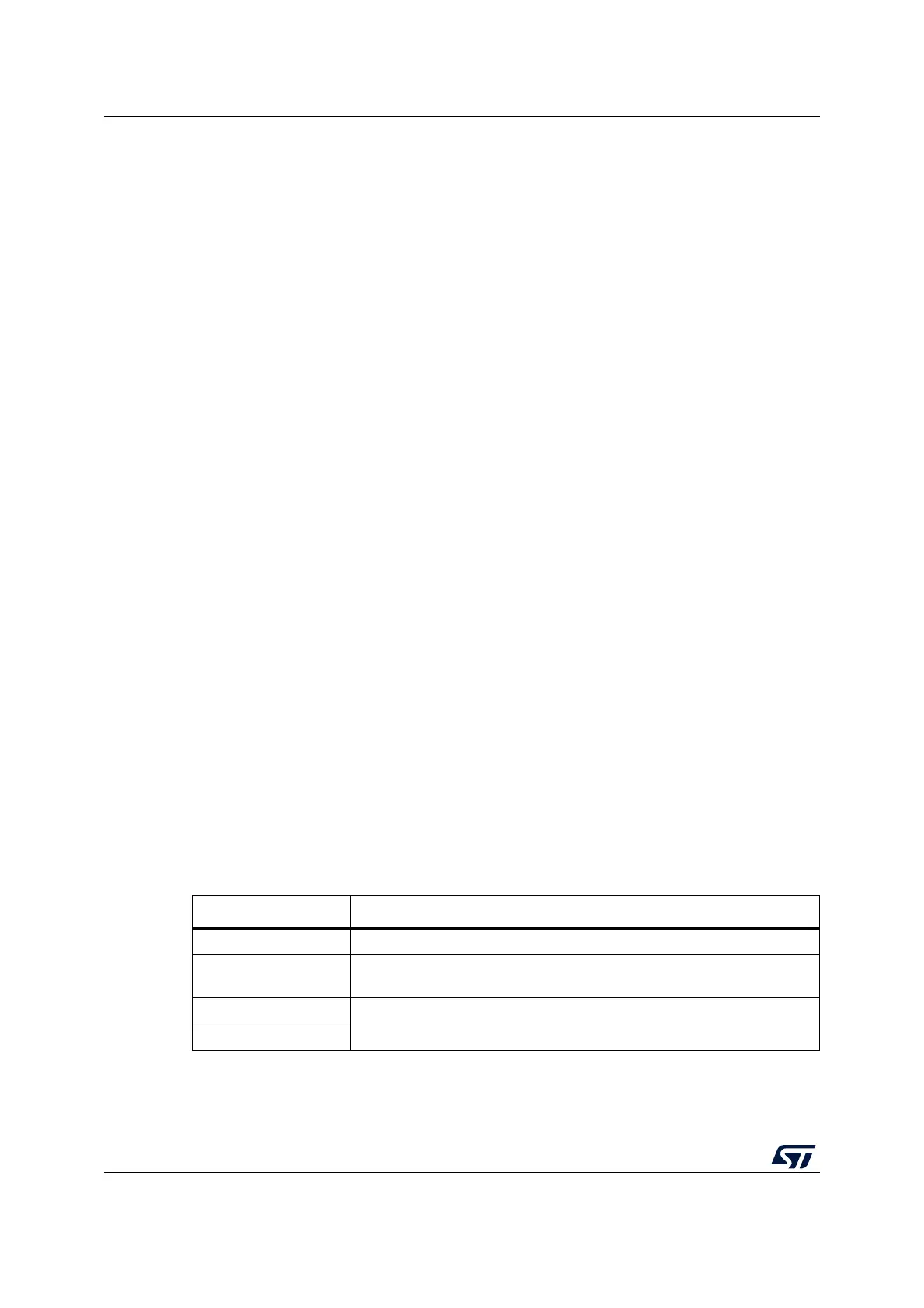
16.5 DAC low-power modes
Table 85. Effect of low-power modes on DAC
Mode Description
Sleep No effect, DAC used with DMA
Stop 0
DAC remains active with a static value, if Sample and hold mode is
selected using LSI clock
Standby
The DAC peripheral is powered down and must be reinitialized after exiting
Standby or Shutdown mode.
Shutdown

 Loading...


