Inter-integrated circuit (I2C) interface RM0444
928/1390 RM0444 Rev 5
The following additional features are also available depending on the product
implementation (see Section 32.3: I2C implementation):
• SMBus specification rev 3.0 compatibility:
– Hardware PEC (Packet Error Checking) generation and verification with ACK
control
– Command and data acknowledge control
– Address resolution protocol (ARP) support
– Host and Device support
– SMBus alert
– Timeouts and idle condition detection
• PMBus rev 1.3 standard compatibility
• Independent clock: a choice of independent clock sources allowing the I2C
communication speed to be independent from the PCLK reprogramming
• Wakeup from Stop mode on address match.
32.3 I2C implementation
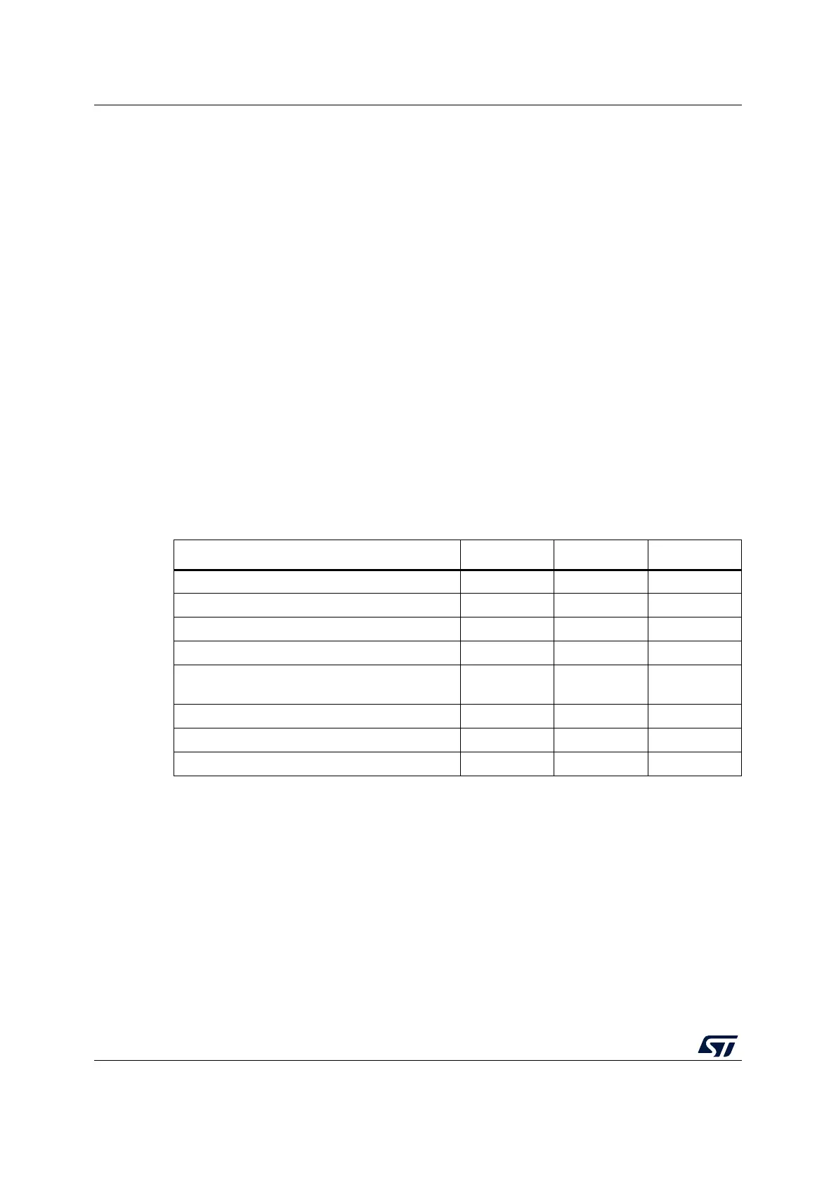
The devices incorporate up to three I²C-bus controllers, I2C1, I2C2, and I2C3, with full or
limited feature sets as shown in the following table.
32.4 I2C functional description
In addition to receiving and transmitting data, this interface converts it from serial to parallel
format and vice versa. The interrupts are enabled or disabled by software. The interface is
connected to the I
2
C bus by a data pin (SDA) and by a clock pin (SCL). It can be connected
with a standard (up to 100 kHz), Fast-mode (up to 400 kHz) or Fast-mode Plus (up to
1MHz) I
2
C bus.
This interface can also be connected to a SMBus with the data pin (SDA) and clock pin
(SCL).
Table 161. STM32G0x1 I2C implementation
I2C features
(1)
1. X = supported.
I2C1 I2C2 I2C3
(2)
2. Applies to STM32G0B1xx and STM32G0C1xx devices only.
7-bit addressing mode X X X
10-bit addressing mode X X X
Standard mode (up to 100 kbit/s) X X X
Fast mode (up to 400 kbit/s) X X X
Fast-mode Plus with 20mA output drive I/Os (up
to 1 Mbit/s)
XXX
Independent clock X X
(2)
/ - -
Wakeup from Stop mode X X
(2)
/ - -
SMBus/PMbus X X
(2)
/ - -

 Loading...


