RM0444 Rev 5 409/1390
RM0444 Digital-to-analog converter (DAC)
441
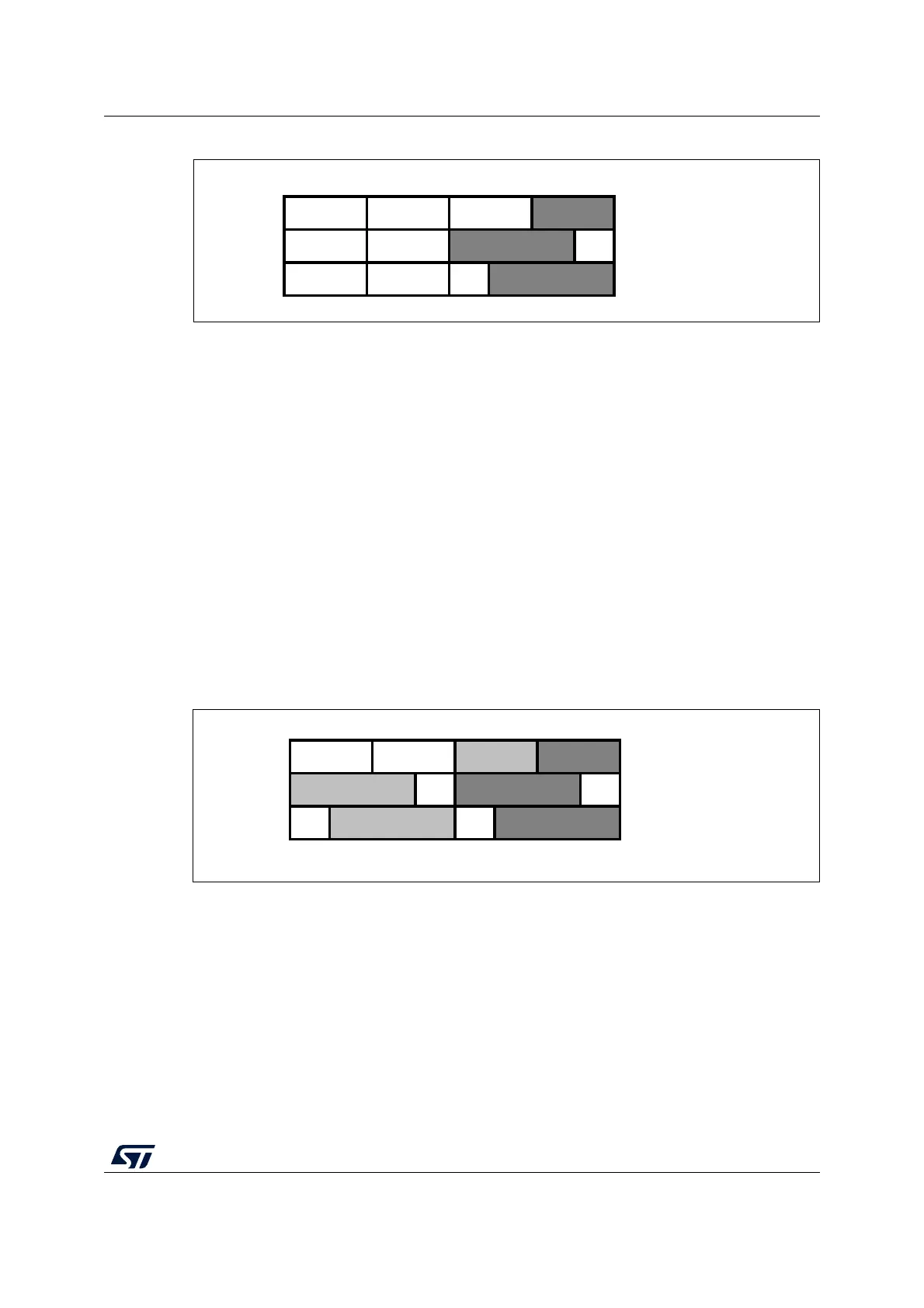
Figure 60. Data registers in single DAC channel mode
• Dual DAC channels (when available)
There are three possibilities:
– 8-bit right alignment: data for DAC channel1 to be loaded into the DAC_DHR8RD
[7:0] bits (stored into the DHR1[11:4] bits) and data for DAC channel2 to be loaded
into the DAC_DHR8RD [15:8] bits (stored into the DHR2[11:4] bits)
– 12-bit left alignment: data for DAC channel1 to be loaded into the DAC_DHR12LD
[15:4] bits (stored into the DHR1[11:0] bits) and data for DAC channel2 to be
loaded into the DAC_DHR12LD [31:20] bits (stored into the DHR2[11:0] bits)
– 12-bit right alignment: data for DAC channel1 to be loaded into the
DAC_DHR12RD [11:0] bits (stored into the DHR1[11:0] bits) and data for DAC
channel2 to be loaded into the DAC_DHR12RD [27:16] bits (stored into the
DHR2[11:0] bits)
Depending on the loaded DAC_DHRyyyD register, the data written by the user is shifted
and stored into DHR1 and DHR2 (data holding registers, which are internal non-memory-
mapped registers). The DHR1 and DHR2 registers are then loaded into the DAC_DOR1
and DOR2 registers, respectively, either automatically, by software trigger or by an external
event trigger.
Figure 61. Data registers in dual DAC channel mode
31 24 15 7 0
8-bit right aligned
12-bit left aligned
12-bit right aligned
ai14710b
31 24 15 7 0
8-bit right aligned
12-bit left aligned
12-bit right aligned
ai14709b

 Loading...


