RM0444 Rev 5 237/1390
RM0444 General-purpose I/Os (GPIO)
247
thus select any one of the possible functions for each I/O. The AF selection signal being
common to the alternate function input and alternate function output, a single channel is
selected for the alternate function input/output of a given I/O.
To know which functions are multiplexed on each GPIO pin refer to the device datasheet.
7.3.8 External interrupt/wakeup lines
All ports have external interrupt capability. To use external interrupt lines, the given pin must
not be configured in analog mode or being used as oscillator pin, so the input trigger is kept
enabled.
Refer to Section 13: Extended interrupt and event controller (EXTI).
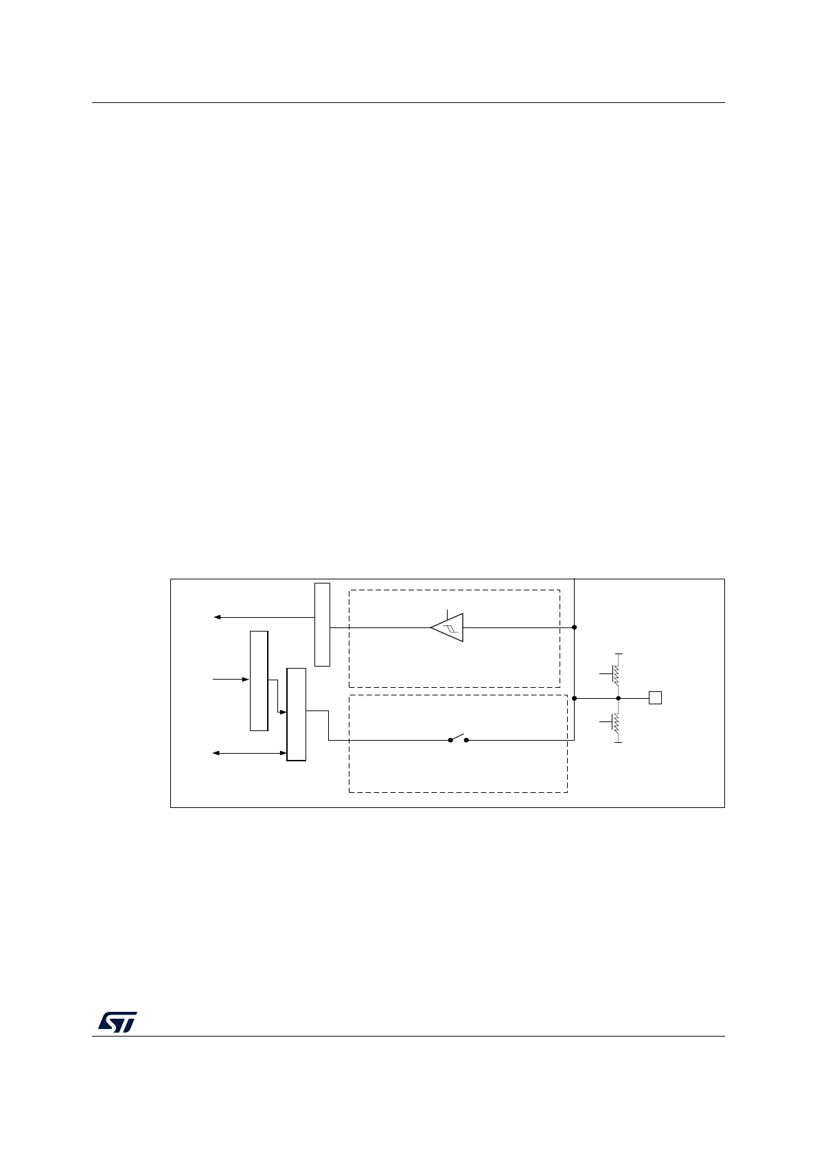
7.3.9 Input configuration
When the I/O port is programmed as input:
• The output buffer is disabled
• The Schmitt trigger input is activated
• The pull-up and pull-down resistors are activated depending on the value in the
GPIOx_PUPDR register
• The data present on the I/O pin are sampled into the input data register every AHB
clock cycle
• A read access to the input data register provides the I/O state
Figure 18 shows the input configuration of the I/O port bit.
Figure 18. Input floating/pull up/pull down configurations
MSv33183V2
Output data register
Bit set/reset registers
Input data register
Read
and EXTI
Output driver
V
SS
V
DDIOx
on/off
on/off
I/O pin
TTL Schmitt trigger
On
Write
Read/write
Pull
up
Pull
down
Input driver

 Loading...


