Inter-integrated circuit (I2C) interface RM0444
968/1390 RM0444 Rev 5
• Configuring the maximum duration of t
IDLE
to 50 µs
32.4.15 SMBus slave mode
This section is relevant only when SMBus feature is supported. Refer to Section 32.3: I2C
implementation.
In addition to I2C slave transfer management (refer to Section 32.4.9: I2C slave mode)
some additional software flowcharts are provided to support SMBus.
SMBus Slave transmitter
When the IP is used in SMBus, SBC must be programmed to ‘1’ in order to allow the PEC
transmission at the end of the programmed number of data bytes. When the PECBYTE bit
is set, the number of bytes programmed in NBYTES[7:0] includes the PEC transmission. In
that case the total number of TXIS interrupts is NBYTES-1 and the content of the
I2C_PECR register is automatically transmitted if the master requests an extra byte after the
NBYTES-1 data transfer.
Caution: The PECBYTE bit has no effect when the RELOAD bit is set.
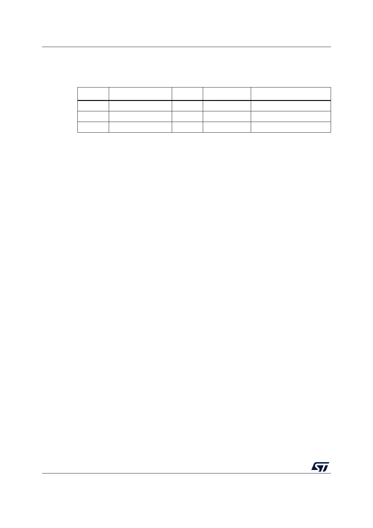
Table 175. Examples of TIMEOUTA settings for various I2CCLK
frequencies
(max t
IDLE
= 50 µs)
f
I2CCLK
TIMEOUTA[11:0] bits TIDLE bit TIMEOUTEN bit t
TIDLE
8 MHz 0x63 1 1 100 x 4 x 125 ns = 50 µs
16 MHz 0xC7 1 1 200 x 4 x 62.5 ns = 50 µs
48 MHz 0x257 1 1 600 x 4 x 20.08 ns = 50 µs

 Loading...


