Analog-to-digital converter (ADC) RM0444
398/1390 RM0444 Rev 5
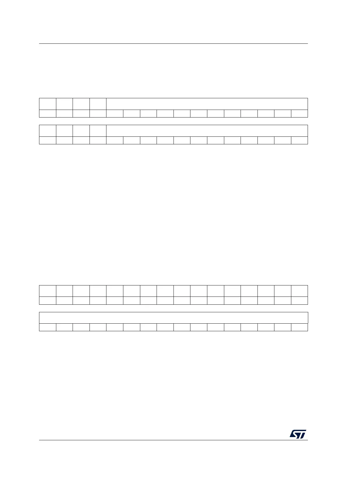
15.12.11 ADC watchdog threshold register (ADC_AWD3TR)
Address offset: 0x2C
Reset value: 0x0FFF 0000
15.12.12 ADC data register (ADC_DR)
Address offset: 0x40
Reset value: 0x0000 0000
31 30 29 28 27 26 25 24 23 22 21 20 19 18 17 16
Res. Res. Res. Res. HT3[11:0]
rw rw rw rw rw rw rw rw rw rw rw rw
1514131211109876543210
Res. Res. Res. Res. LT3[11:0]
rw rw rw rw rw rw rw rw rw rw rw rw
Bits 31:28 Reserved, must be kept at reset value.
Bits 27:16 HT3[11:0]: Analog watchdog 3 higher threshold
These bits are written by software to define the higher threshold for the analog watchdog.
Refer to Section 15.7: Analog window watchdog (AWD1EN, AWD1SGL, AWD1CH, ADC_AWDxCR,
ADC_AWDxTR) on page 369.
Bits 15:12 Reserved, must be kept at reset value.
Bits 11:0 LT3[11:0]: Analog watchdog 3lower threshold
These bits are written by software to define the lower threshold for the analog watchdog.
Refer to Section 15.7: Analog window watchdog (AWD1EN, AWD1SGL, AWD1CH, ADC_AWDxCR,
ADC_AWDxTR) on page 369.
31 30 29 28 27 26 25 24 23 22 21 20 19 18 17 16
Res. Res. Res. Res. Res. Res. Res. Res. Res. Res. Res. Res. Res. Res. Res. Res.
1514131211109876543210
DATA[15:0]
rrrrrrrrrrrrrrrr
Bits 31:16 Reserved, must be kept at reset value.
Bits 15:0 DATA[15:0]: Converted data
These bits are read-only. They contain the conversion result from the last converted channel. The data
are left- or right-aligned as shown in Figure 44: Data alignment and resolution (oversampling disabled:
OVSE = 0) on page 363.
Just after a calibration is complete, DATA[6:0] contains the calibration factor.

 Loading...


