Inter-integrated circuit (I2C) interface RM0444
966/1390 RM0444 Rev 5
Specific address (Slave mode)
The specific SMBus addresses must be enabled if needed. Refer to Bus idle detection on
page 965 for more details.
• The SMBus Device Default Address (0b1100 001) is enabled by setting the SMBDEN
bit in the I2C_CR1 register.
• The SMBus Host Address (0b0001 000) is enabled by setting the SMBHEN bit in the
I2C_CR1 register.
• The Alert Response Address (0b0001100)
is enabled by setting the ALERTEN bit in the
I2C_CR1 register.
Packet error checking
PEC calculation is enabled by setting the PECEN bit in the I2C_CR1 register. Then the PEC
transfer is managed with the help of a hardware byte counter: NBYTES[7:0] in the I2C_CR2
register. The PECEN bit must be configured before enabling the I2C.
The PEC transfer is managed with the hardware byte counter, so the SBC bit must be set
when interfacing the SMBus in slave mode. The PEC is transferred after NBYTES-1 data
have been transferred when the PECBYTE bit is set and the RELOAD bit is cleared. If
RELOAD is set, PECBYTE has no effect.
Caution: Changing the PECEN configuration is not allowed when the I2C is enabled.
Timeout detection
The timeout detection is enabled by setting the TIMOUTEN and TEXTEN bits in the
I2C_TIMEOUTR register. The timers must be programmed in such a way that they detect a
timeout before the maximum time given in the SMBus specification.
• t
TIMEOUT
check
In order to enable the t
TIMEOUT
check, the 12-bit TIMEOUTA[11:0] bits must be
programmed with the timer reload value in order to check the t
TIMEOUT
parameter. The
TIDLE bit must be configured to ‘0’ in order to detect the SCL low level timeout.
Then the timer is enabled by setting the TIMOUTEN in the I2C_TIMEOUTR register.
If SCL is tied low for a time greater than (TIMEOUTA+1) x 2048 x t
I2CCLK
, the TIMEOUT
flag is set in the I2C_ISR register.
Refer to Table 173: Examples of TIMEOUTA settings for various I2CCLK frequencies
(max t
TIMEOUT
= 25 ms).
Caution: Changing the TIMEOUTA[11:0] bits and TIDLE bit configuration is not allowed when the
TIMEOUTEN bit is set.
• t
LOW:SEXT
and t
LOW:MEXT
check
Depending on if the peripheral is configured as a master or as a slave, The 12-bit
TIMEOUTB timer must be configured in order to check t
LOW:SEXT
for a slave and
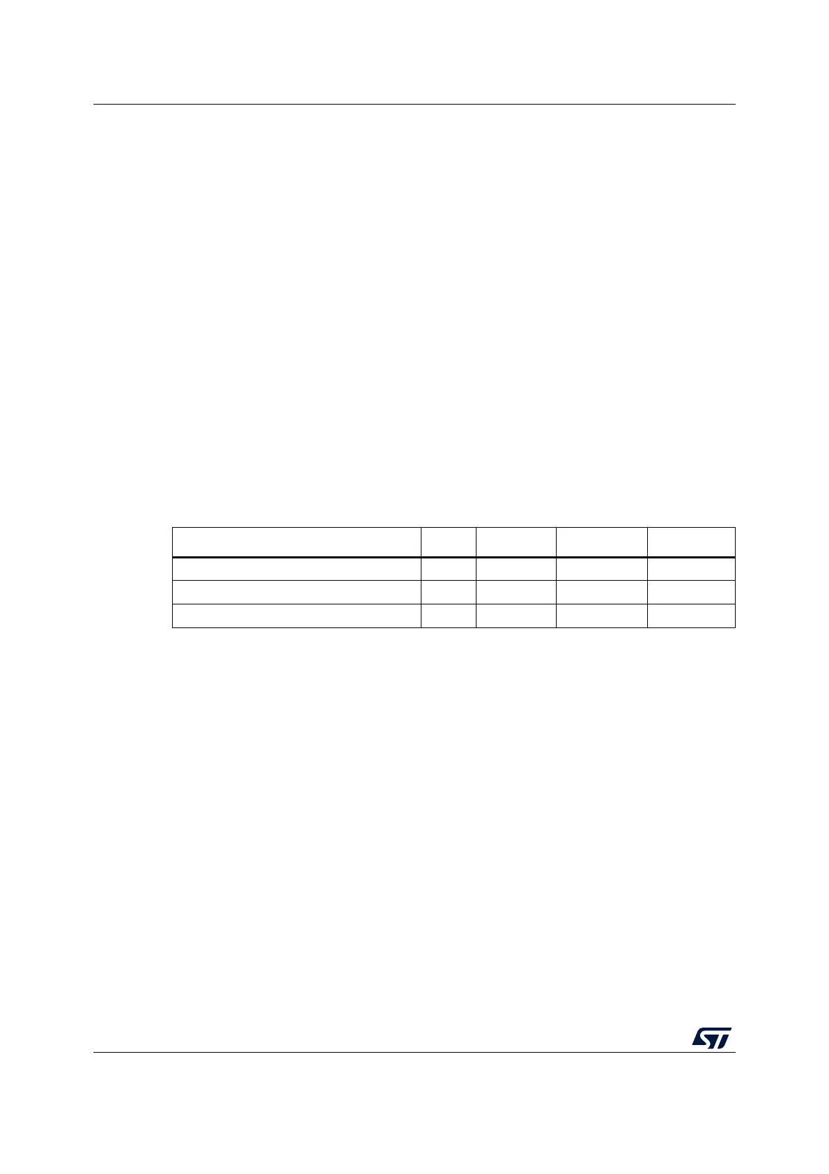
Table 172. SMBus with PEC configuration
Mode SBC bit RELOAD bit AUTOEND bit PECBYTE bit
Master Tx/Rx NBYTES + PEC+ STOP x 0 1 1
Master Tx/Rx NBYTES + PEC + ReSTART x 0 0 1
Slave Tx/Rx with PEC 1 0 x 1

 Loading...


