AES hardware accelerator (AES) RM0444
510/1390 RM0444 Rev 5
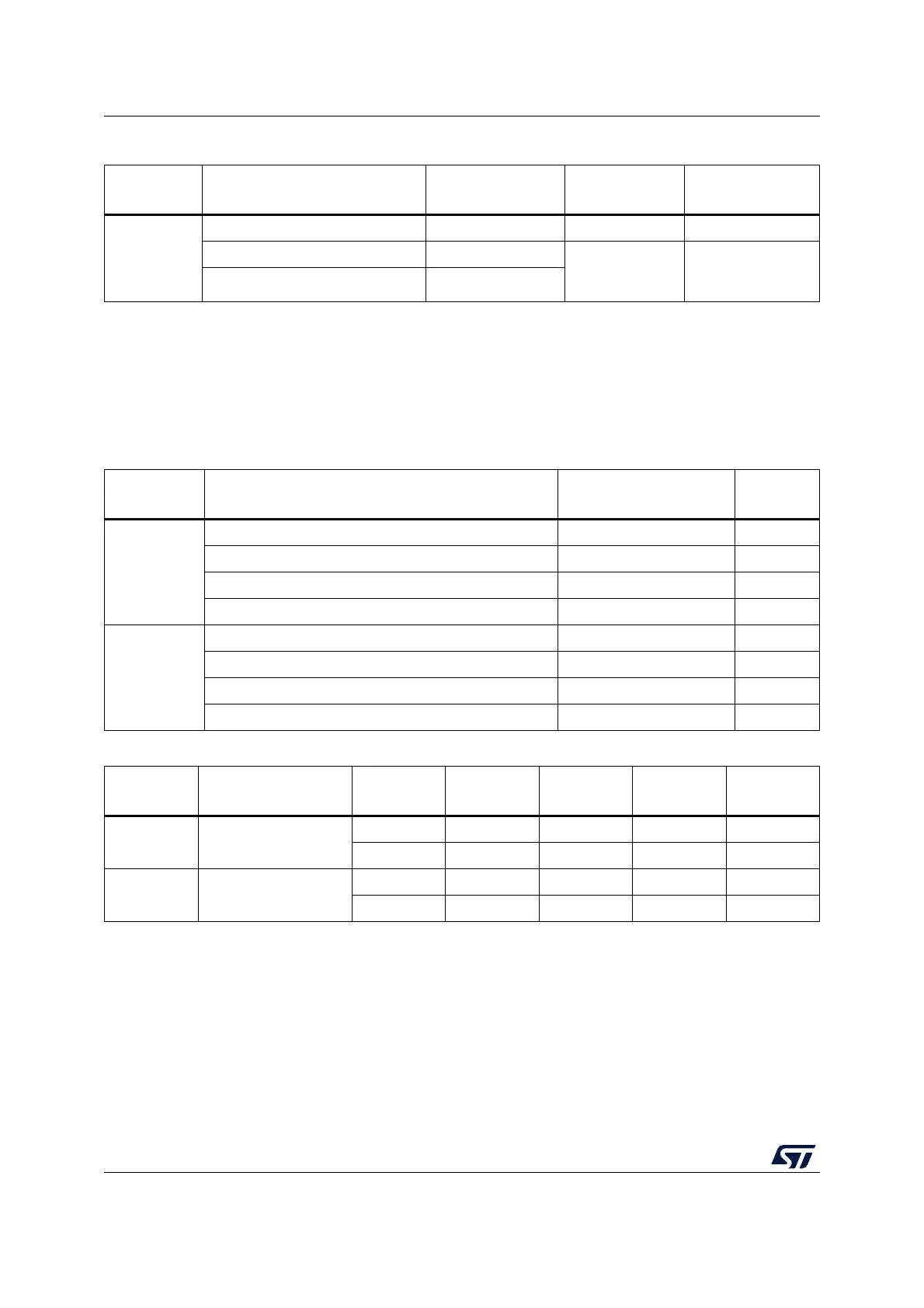
20.6 AES processing latency
The tables below summarize the latency to process a 128-bit block for each mode of
operation.
Table 108. AES interrupt requests
Interrupt
acronym
AES
interrupt event Event flag Enable bit
Interrupt clear
method
AES
computation completed flag CCF CCFIE set CCFC
(1)
read error flag RDERR
ERRIE set ERRC
(1)
write error flag WRERR
1. Bit of the AES_CR register.
Table 109. Processing latency for ECB, CBC and CTR
Key size Mode of operation Algorithm
Clock
cycles
128-bit
Mode 1: Encryption ECB, CBC, CTR 51
Mode 2: Key derivation - 59
Mode 3: Decryption ECB, CBC, CTR 51
Mode 4: Key derivation then decryption ECB, CBC 106
256-bit
Mode 1: Encryption ECB, CBC, CTR 75
Mode 2: Key derivation - 82
Mode 3: Decryption ECB, CBC, CTR 75
Mode 4: Key derivation then decryption ECB, CBC 145
Table 110. Processing latency for GCM and CCM (in clock cycles)
Key size Mode of operation Algorithm Init Phase
Header
phase
(1)
Payload
phase
(1)
Tag phase
(1)
128-bit
Mode 1: Encryption/
Mode 3: Decryption
GCM64355159
CCM 63 55 114 58
256-bit
Mode 1: Encryption/
Mode 3: Decryption
GCM88357575
CCM 87 79 162 82
1. Data insertion can include wait states forced by AES on the AHB bus (maximum 3 cycles, typical 1 cycle).

 Loading...


