RM0444 Rev 5 1089/1390
RM0444 Low-power universal asynchronous receiver transmitter (LPUART)
1138
34.4 LPUART functional description
34.4.1 LPUART block diagram
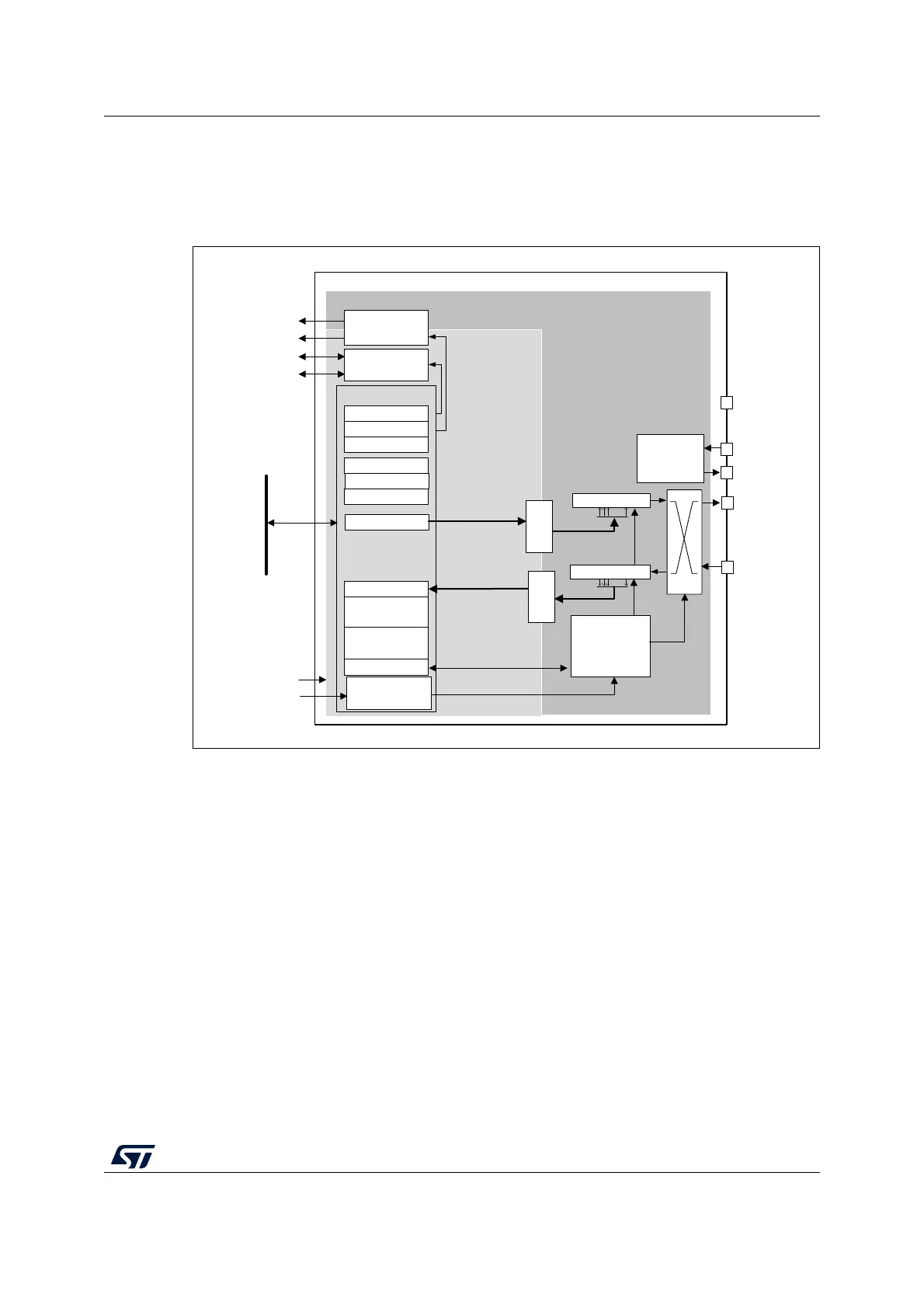
Figure 341. LPUART block diagram
The simplified block diagram given in Figure 341 shows two fully independent clock
domains:
• The lpuart_pclk clock domain
The lpuart_pclk clock signal feeds the peripheral bus interface. It must be active when
accesses to the LPUART registers are required.
• The lpuart_ker_ck kernel clock domain
The lpuart_ker_ck is the LPUART clock source. It is independent of the lpuart_pclk
and delivered by the RCC. So, the LPUART registers can be written/read even when
the lpuart_ker_ck is stopped.
When the dual clock domain feature is disabled, the lpuart_ker_ck is the same as the
lpuart_pclk clock.
There is no constraint between lpuart_pclk and lpuart_ker_ck: lpuart_ker_ck can be
faster or slower than lpuart_pclk, with no more limitation than the ability for the software to
manage the communication fast enough.
MSv40858V3
LPUART_TDR
LPUART_RDR
LPUART_
GTPR
LPUART_BRR
LPUART_CR3
LPUART_RQR
LPUART_CR2
RX Shift Reg
COM Controller
RxFIFO
lpuart_pclk
clock domain
LPUART
TX
RX
lpuart_ker_ck
32-bit APB bus
LPUART_ICR
LPUART_ISR
...
TX Shift Reg
...
CTS/NSS
RTS/DE
LPUART_CR1
LPUART_
RTOR
Baudrate
generator &
orversampling
lpuart_ker_ck clock domain
DMA Interface
lpuart_pclk
lpuart_tx_dma
lpuart_rx_dma
lpuart_it
lpuart_wkup
IRQ Interface
CK
LPUART_
PRESC
lpuart_ker_ck_pres
Hardware
flow control
TxFIFO

 Loading...


