RM0444 Rev 5 455/1390
RM0444 Comparator (COMP)
458
18.6.3 Comparator 3 control and status register (COMP3_CSR)
Address offset: 0x08
System reset value: 0x0000 0000
Bits 9:8 INPSEL[1:0]: Comparator 2 signal selector for non-inverting input
This bitfield is controlled by software (if not locked). It selects the signal for the non-inverting
input COMP2_INP of the comparator 2 (also see the WINMODE bit):
00: PB4
01: PB6
10: PA3
11: None (open)
Bits 7:4 INMSEL[3:0]: Comparator 2 signal selector for inverting input INM
This bitfield is controlled by software (if not locked). It selects the signal for the inverting
input COMP2_INM of the comparator 2:
0000: 1/4 V
REFINT
0001: 1/2 V
REFINT
0010: 3/4 V
REFINT
0011: V
REFINT
0100: DAC channel 1
0101: DAC channel 2
0110: PB3
0111: PB7
1000: PA2
> 1000: 1/4 V
REFINT
Bits 3:1 Reserved, must be kept at reset value
Bit 0 EN: Comparator 2 enable bit
This bit is controlled by software (if not locked). It enables the comparator 2:
0: Disable
1: Enable
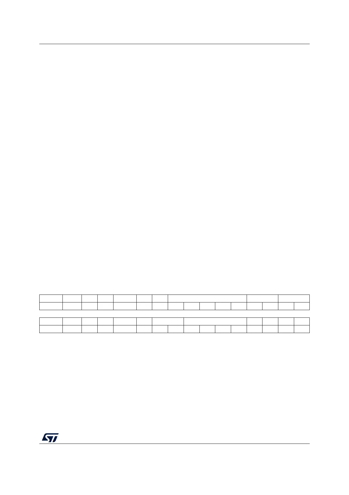
31 30 29 28 27 26 25 24 23 22 21 20 19 18 17 16
LOCK VALUE Res. Res. Res. Res. Res. BLANKSEL PWRMODE HYST
rw r rwrwrwrwrwrwrwrwrw
15 141312 11 109876543210
POLARITY WINOUT Res. Res. WINMODE Res. INPSEL INMSEL Res. Res. Res. EN
rw rw rw rw rw rw rw rw rw rw
Bit 31 LOCK: COMP3_CSR register lock
This bit is set by software and cleared by a system reset. It locks the comparator 3 control
bits. When locked, all register bits are read-only.
0: Not locked
1: Locked
Bit 30 VALUE: Comparator 3 output status
This bit is read-only. It reflects the level of the comparator 3 output after the polarity selector
and blanking, as indicated in Figure 68.
Bits 29:25 Reserved, must be kept at reset value

 Loading...


