Advanced-control timer (TIM1) RM0444
554/1390 RM0444 Rev 5
TIMx_CR1 register is updated by hardware and must not be changed by software. Refer to
the Center-aligned mode (up/down counting) on page 535.
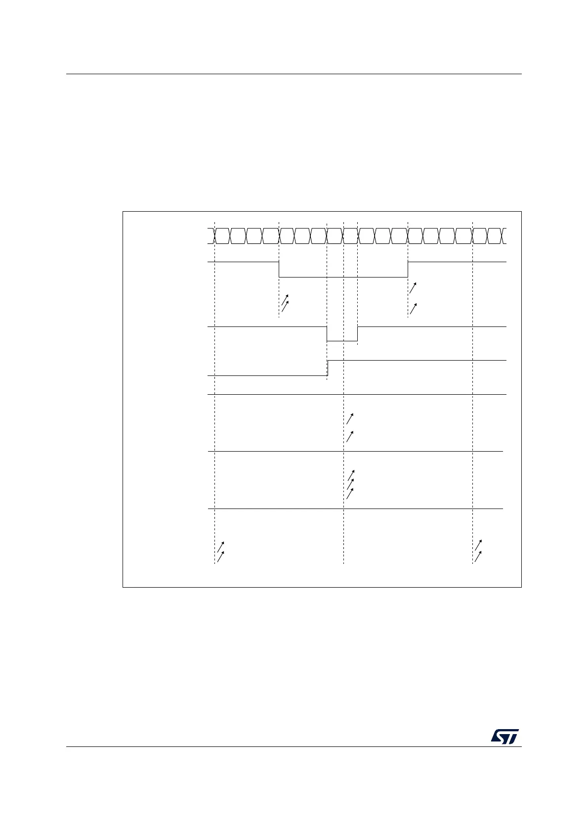
Figure 137 shows some center-aligned PWM waveforms in an example where:
• TIMx_ARR=8,
• PWM mode is the PWM mode 1,
• The flag is set when the counter counts down corresponding to the center-aligned
mode 1 selected for CMS=01 in TIMx_CR1 register.
Figure 137. Center-aligned PWM waveforms (ARR=8)
Hints on using center-aligned mode
• When starting in center-aligned mode, the current up-down configuration is used. It
means that the counter counts up or down depending on the value written in the DIR bit
CCxIF
01234567876 5432 101
Counter register
CCRx = 4
OCxREF
CMS=01
CMS=10
CMS=11
CCxIF
CCRx=7
OCxREF
CMS=10 or 11
CCxIF
CCRx=8
OCxREF
CMS=01
CMS=10
CMS=11
‘1’
CCxIF
CCRx>8
OCxREF
CMS=01
CMS=10
CMS=11
‘1’
CCxIF
CCRx=0
OCxREF
CMS=01
CMS=10
CMS=11
‘0’
AI14681b

 Loading...


