Reset and clock control (RCC) RM0444
178/1390 RM0444 Rev 5
5.4 RCC registers
Unless otherwise specified, the RCC registers support word, half-word, and byte access,
without any wait state.
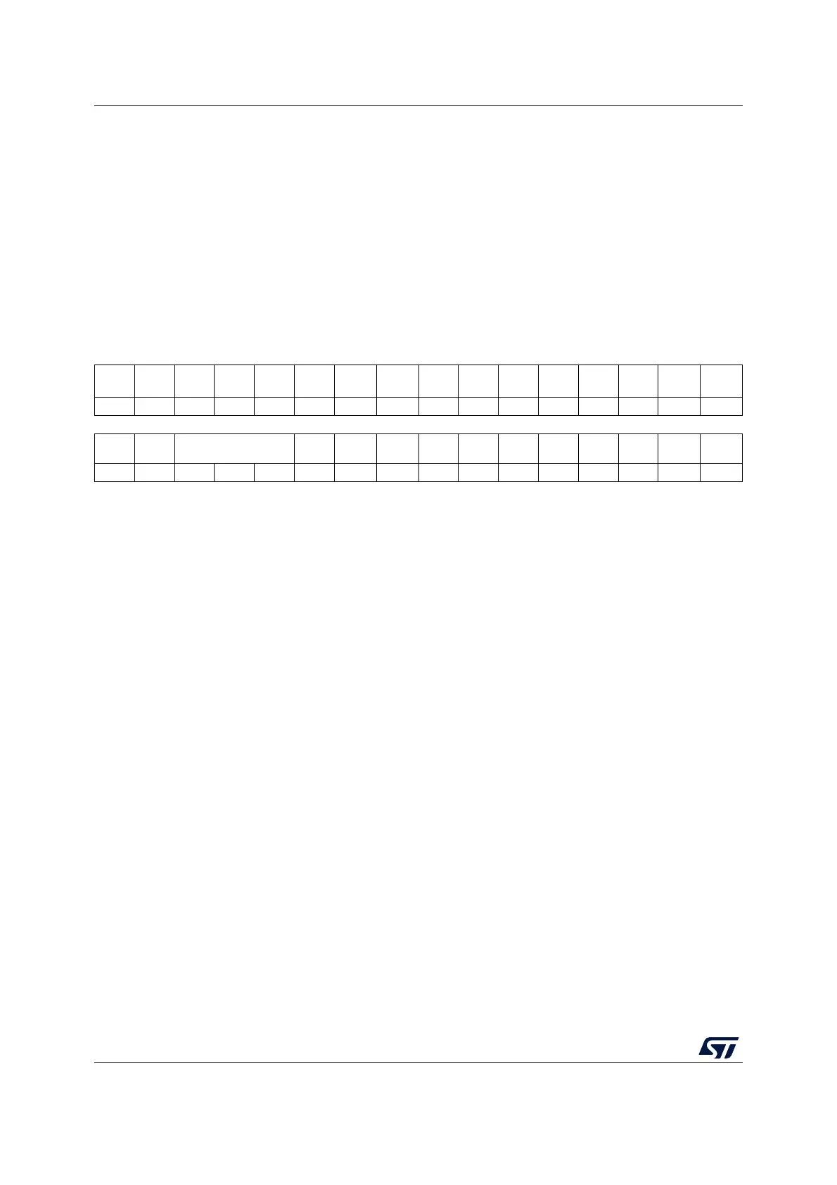
5.4.1 Clock control register (RCC_CR)
Address offset: 0x00
Power-on reset value: 0x0000 0500
Other types of reset: same as power-on reset, except HSEBYP bit that keeps its previous
value.
31 30 29 28 27 26 25 24 23 22 21 20 19 18 17 16
Res. Res. Res. Res. Res. Res.
PLL
RDY
PLLON
HSI48
RDY
(1)
HSI48
ON
(1)
Res. Res.
CSS
ON
HSE
BYP
HSE
RDY
HSE
ON
r rw r rw rs rw r rw
1514131211109 8 765432 1 0
Res. Res. HSIDIV[2:0]
HSI
RDY
HSI
KERON
HSION Res. Res. Res. Res. Res. Res. Res. Res.
rw rw rw r rw rw
1. Only significant on devices integrating the corresponding peripheral, otherwise reserved. Refer to Section 1.4: Availability
of peripherals.
Bits 31:26 Reserved, must be kept at reset value.
Bit 25 PLLRDY: PLL clock ready flag
Set by hardware to indicate that the PLL is locked.
0: PLL unlocked
1: PLL locked
Bit 24 PLLON: PLL enable
Set and cleared by software to enable the PLL.
Cleared by hardware when entering Stop, Standby or Shutdown mode. This bit cannot be
reset if the PLL clock is used as the system clock.
0: PLL OFF
1: PLL ON
Bit 23 HSI48RDY: HSI48 clock ready flag
(1)
The flag is set when the HSI48 clock is ready for use.
Bit 22 HSI48ON: HSI48 RC oscillator enable
(1)
0: Disable
1: Enable
Bits 21:20 Reserved, must be kept at reset value.
Bit 19 CSSON: Clock security system enable
Set by software to enable the clock security system. When CSSON is set, the clock detector
is enabled by hardware when the HSE oscillator is ready, and disabled by hardware if a HSE
clock failure is detected. This bit is set only and is cleared by reset.
0: Clock security system OFF (clock detector OFF)
1: Clock security system ON (Clock detector ON if the HSE oscillator is stable, OFF if not).

 Loading...


