RM0444 Rev 5 271/1390
RM0444 Interconnect matrix
276
9.3 Interconnection details
9.3.1 From TIM1, TIM2, TIM3, TIM4, TIM15, TIM16, and TIM17,
to TIM1, TIM2, TIM3, TIM4, and TIM15
Purpose
Some of the TIMx timers are linked together internally for timer synchronization or chaining.
When one timer is configured in master mode, it can reset, start, stop or clock the counter of
another timer configured in slave mode.
A description of the feature is provided in: Section 22.3.19: Timer synchronization.
The modes of synchronization are detailed in:
• Section 21.3.26: Timer synchronization for advanced-control timer TIM1
• Section 22.3.18: Timers and external trigger synchronization for general-purpose
timers TIM2/TIM3/TIM4
• Section 25.4.19: External trigger synchronization (TIM15 only) for general-purpose
timer TIM15
VREFINT
- - - - - - - - - 9.3.8 - - - - - -
HSE
- - - - 9.3.5 - - 9.3.5 - - - - - - - - -
LSE
- 9.3.5 - - - - 9.3.5 - - - - - - - - - -
LSI
- - - - - - 9.3.5 - - - - - - - - - -
MCO
- - - - 9.3.5 - - 9.3.5 - - - - - - - - -
MCO2
- - - - 9.3.5 - - 9.3.5 - - - - - - - - -
EXTI
- - - - - - - - - - 9.3.2 9.3.4 - - - - -
RTC and
TAMP
- - - - 9.3.5 - 9.3.5 - 9.3.6 9.3.6 - - - - - - -
COMP1
9.3.9 9.3.9 9.3.9 9.3.9 - 9.3.9 9.3.9 9.3.9 9.3.6 9.3.6 - - - - - - -
COMP2
9.3.9 9.3.9 9.3.9 9.3.9 - 9.3.9 9.3.9 9.3.9 9.3.6 9.3.6 - - - - - - -
COMP3
9.3.9 9.3.9 9.3.9 9.3.9 - 9.3.9 9.3.9 9.3.9 9.3.6 9.3.6 - - - - - - -
SYST
ERR
9.3.10 9.3.10 9.3.10 9.3.10 - 9.3.10 9.3.10 9.3.10 - - - - - - - - -
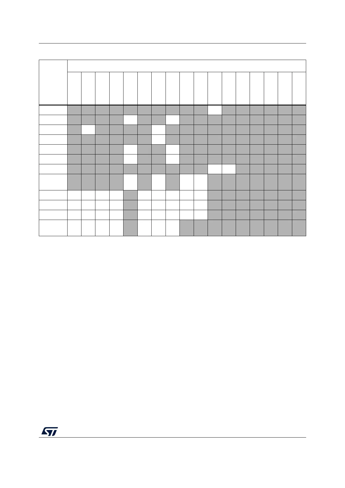
1. Numbers in the table are links to corresponding sub-sections in Section 9.3: Interconnection details.
2. The “-” symbol in grayed cells means “no interconnection”.
Table 45. Interconnect matrix
(1)(2)
(continued)
Source
Destination
TIM1
TIM2
TIM3
TIM4
TIM14
TIM15
TIM16
TIM17
LPTIM1
LPTIM2
ADC
DAC
DMAMUX
COMP1
COMP2
COMP3
IRTIM

 Loading...


