Advanced-control timer (TIM1) RM0444
562/1390 RM0444 Rev 5
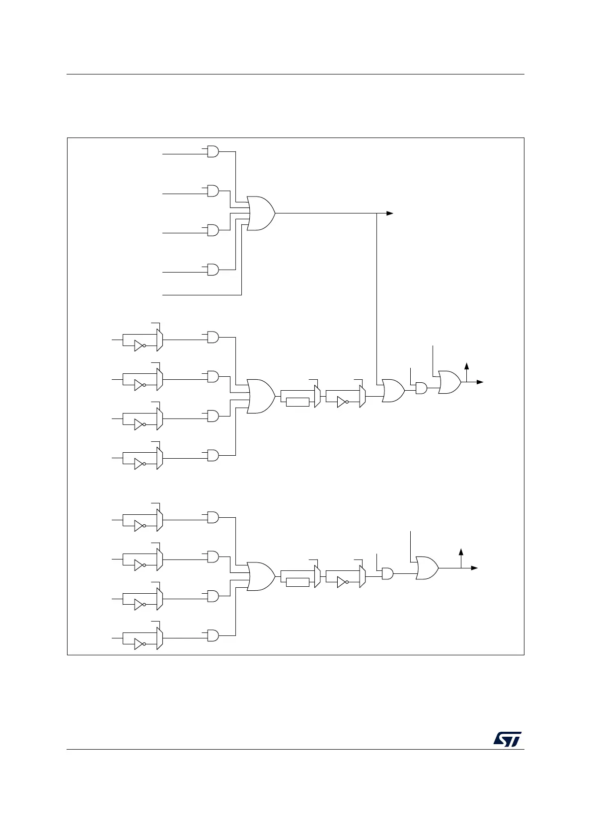
All sources are ORed before entering the timer BRK or BRK2 inputs, as per Figure 144
below.
Figure 144. Break and Break2 circuitry overview
1. Available on STM32G0B1xx and STM32G0C1xx salestypes only.
Note: An asynchronous (clockless) operation is only guaranteed when the programmable filter is
disabled. If it is enabled, a fail safe clock mode (for example by using the internal PLL and/or
the CSS) must be used to guarantee that break events are handled.
MSv66283V1
COMP2
output
BK2CMP2E
BK2CMP2P
COMP1
output
BK2CMP1E
BK2CMP1P
BKIN2 inputs
from AF
controller
BK2INE
BK2INP
BK2F[3:0]
Filter
BK2P
Application break requests
COMP2
output
BKCMP2E
BKCMP2P
COMP1
output
BKCMP1E
BKCMP1P
BKIN inputs
from AF
controller
BKINE
BKINP
BKF[3:0]
Filter
BKP
Application break requests
ECC LOCK
Parity LOCK
PVD LOCK
Lockup LOCK
Double ECC Error
RAM parity Error
PVD
Core Lockup
CSS
SBIF flag
System break requests
Software break requests: B2G
B2IF flag
BRK2 request
BKE
BRK request
BIF flag
Software break requests: BG
BK2E
COMP3
output
(1)
BKCMP3E
BKCMP3P
COMP3
output
(1)
BK2CMP3E
BK2CMP3P

 Loading...


