Memory and bus architecture RM0444
56/1390 RM0444 Rev 5
2 Memory and bus architecture
2.1 System architecture
The main system consists of:
• Two masters:
–Cortex
®
-M0+ core
– General-purpose DMA
• Three slaves:
– Internal SRAM
– Internal Flash memory
– AHB with AHB-to-APB bridge that connects all the APB peripherals
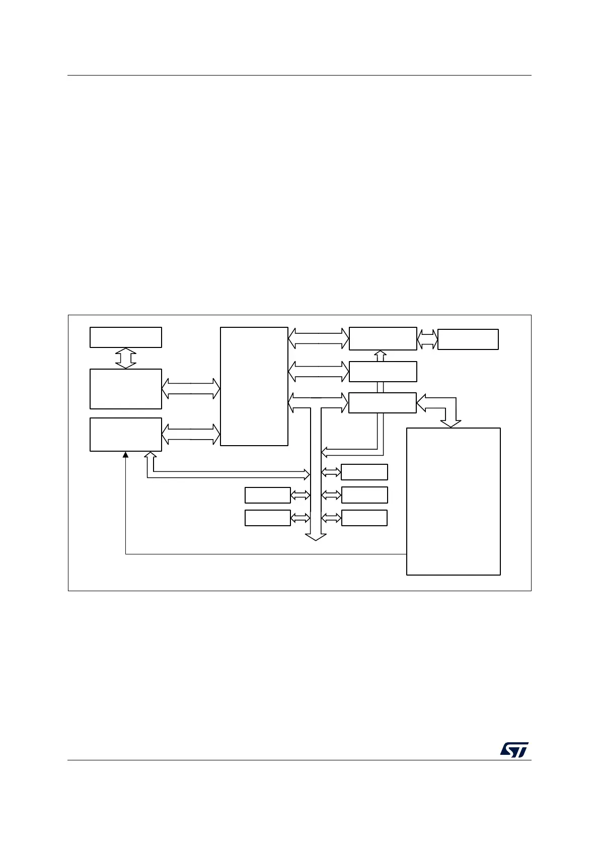
These are interconnected using a multilayer AHB bus architecture as shown in Figure 1.
Figure 1. System architecture
System bus (S-bus)
This bus connects the system bus of the Cortex
®
-M0+ core (peripheral bus) to a bus matrix
that manages the arbitration between the core and the DMA.
DMA bus
This bus connects the AHB master interface of the DMA to the bus matrix that manages the
access of CPU and DMA to SRAM, Flash memory and AHB/APB peripherals.
Bus matrix
Flash memory
interface
SRAM
GPIO Ports
A,B,C,D,E,F
AHB-to-APB
bridge
Arm
®
Cortex
®
-M0+
core
DMA1/2
DMAMUX
channels 1 to 12
System bus
RCC
CRC
DMA requests
Flash memory
AHB
APB
SYSCFG,
ADC, DAC,
COMP1, COMP2, COMP3
TIM1, TIM2, TIM3, TIM4
TIM6, TIM7,
TIM14 to TIM17,
LPTIM1, LPTIM2,
UCPD1, UCPD2,
IWDG, WWDG,
RTC, PWR,
I2C1, I2C2, I2C3
USART1 to USART6,
LPUART1, LPUART2
SPI1/I2S1, SPI2/I2S2, SPI3
USB
FDCAN
HDMI-CEC,
DBGMCU
DMA bus
AES
RNG EXTI
IOPORT

 Loading...


