Power control (PWR) RM0444
138/1390 RM0444 Rev 5
4.3.7 Stop 1 mode
The Stop 1 mode is the same as Stop 0 mode except that the main regulator is off, and only
the low-power regulator is on. Stop 1 mode can be entered from Run mode and from Low-
power run mode.
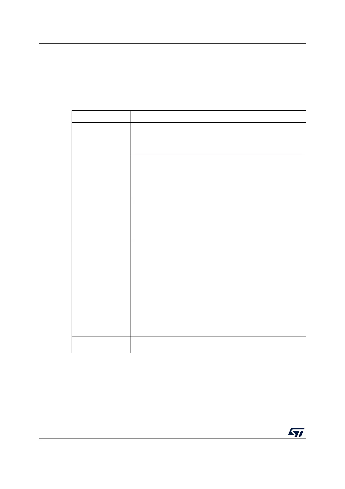
Refer to Table 31: Stop 1 mode summary for details on how to enter and exit Stop 1 mode.
Table 31. Stop 1 mode summary
Characteristic Description
Mode entry
WFI (Wait for Interrupt) or WFE (Wait for Event) while:
– SLEEPDEEP bit is set in Cortex
®
-M0+ System Control register
– No interrupt (for WFI) or event (for WFE) is pending
– LPMS = “001” in PWR_CR1
On Return from ISR while:
– SLEEPDEEP bit is set in Cortex
®
-M0+ System Control register
– SLEEPONEXIT = 1
– No interrupt is pending
– LPMS = “001” in PWR_CR1
Note: To enter Stop 1 mode, all EXTI Line pending bits (in EXTI rising
edge pending register 1 (EXTI_RPR1) and EXTI falling edge
pending register 1 (EXTI_FPR1)), and the peripheral flags
generating wakeup interrupts must be cleared. Otherwise, the Stop
1 mode entry procedure is ignored and program execution
continues.
Mode exit
If WFI or Return from ISR was used for entry
Any EXTI Line configured in Interrupt mode (the corresponding EXTI
Interrupt vector must be enabled in the NVIC). The interrupt source can
be external interrupts or peripherals with wakeup capability. Refer to
Table 58: Vector table.
If WFE was used for entry and SEVONPEND = 0:
Any EXTI Line configured in event mode. Refer to Section 13.3.2: EXTI
direct event input wakeup.
If WFE was used for entry and SEVONPEND = 1:
Any EXTI Line configured in Interrupt mode (even if the corresponding
EXTI Interrupt vector is disabled in the NVIC). The interrupt source can
be external interrupts or peripherals with wakeup capability. Refer to
Table 58: Vector table.
Wakeup event: refer to Section 13.3.2: EXTI direct event input wakeup
Wakeup latency
Longest wakeup time between HSI16 wakeup time and regulator wakeup
time from Low-power mode + Flash wakeup time from Stop 1 mode.

 Loading...


