Power control (PWR) RM0444
132/1390 RM0444 Rev 5
Exiting Low-power run mode
To exit Low-power run mode, proceed as follows:
1. Force the regulator in main mode by clearing the LPR bit in the Power control register 1
(PWR_CR1).
2. Wait until REGLPF bit is cleared in the Power status register 2 (PWR_SR2).
3. Increase the system clock frequency.
Refer to Table 27: Low-power run on how to exit Low-power run mode.
4.3.3 Low-power modes
Entering low-power modes
The MCU enters low-power modes by executing the WFI (wait for interrupt), or WFE (wait
for event) instructions, or when the SLEEPONEXIT bit in the Cortex
®
-M0+ system control
register is set on return from ISR.
Entering low-power mode through WFI or WFE is executed only if no interrupt is pending or
no event is pending.
Exiting low-power modes
The MCU exits Sleep and Stop low-power modes in a way depending on how the low-power
mode was entered:
• If the WFI instruction or Return from ISR was used to enter low-power mode, any
peripheral interrupt acknowledged by the NVIC can wake up the device.
• If the WFE instruction is used to enter low-power mode, the MCU exits low-power
mode as soon as an event occurs. The wakeup event can be generated either by:
– NVIC IRQ interrupt.
When SEVONPEND = 0 in the Cortex
®
-M0+ system control register: by enabling
an interrupt in the peripheral control register and in the NVIC. When the MCU
resumes from WFE, the peripheral interrupt pending bit and the NVIC peripheral
IRQ channel pending bit (in the NVIC interrupt clear pending register) have to be
cleared.
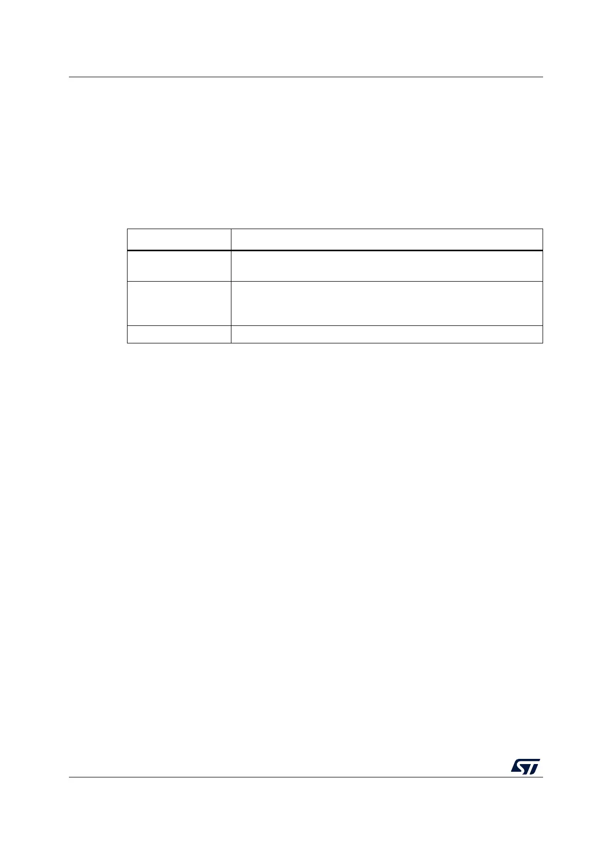
Table 27. Low-power run
Low-power run mode Description
Mode entry
Decrease the system clock frequency below 2 MHz
LPR = 1
Mode exit
LPR = 0
Wait until REGLPF = 0
Increase the system clock frequency
Wakeup latency Regulator wakeup time from low-power mode

 Loading...


