RM0444 Rev 5 723/1390
RM0444 General-purpose timers (TIM14)
740
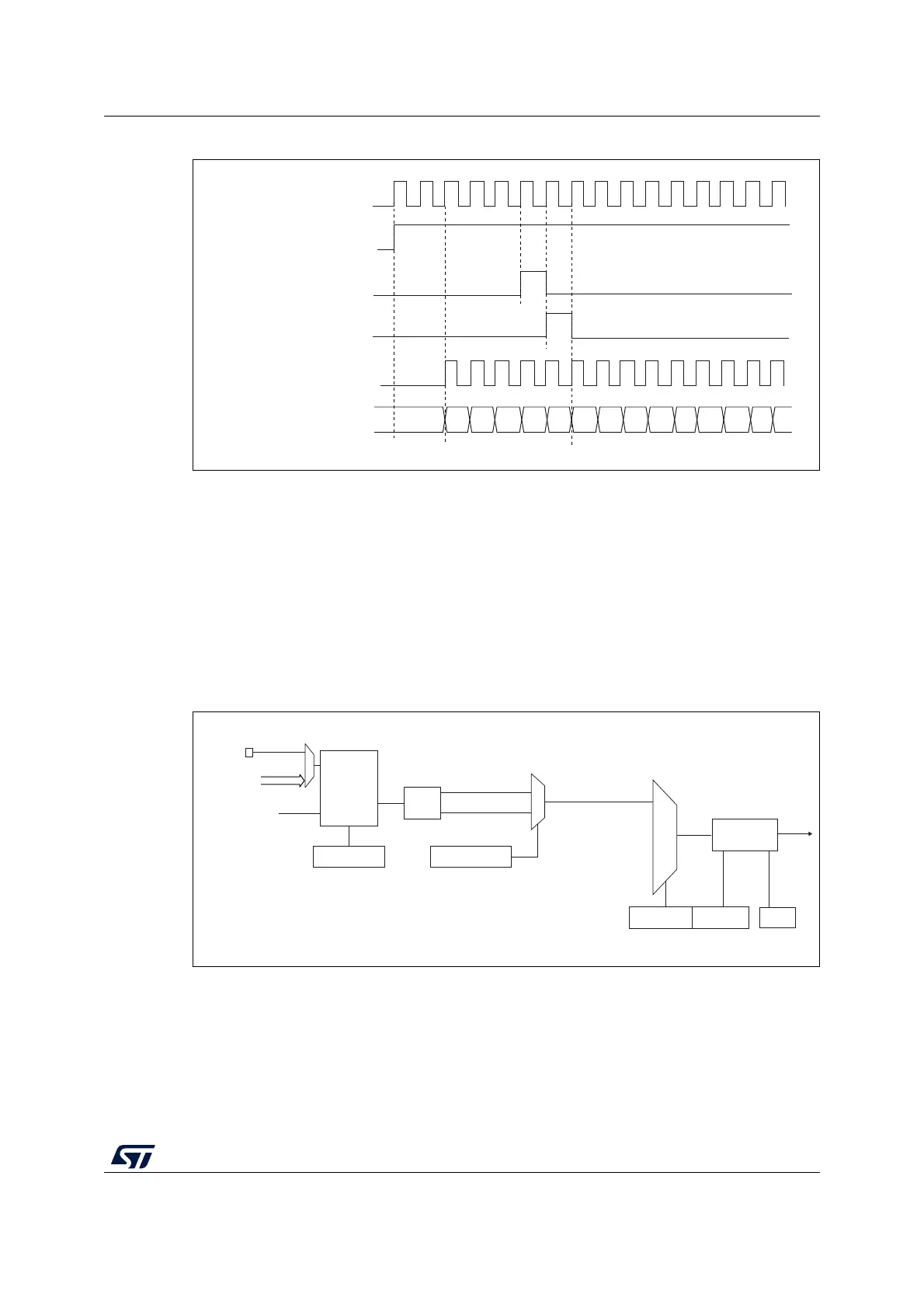
Figure 230. Control circuit in normal mode, internal clock divided by 1
24.3.4 Capture/compare channels
Each Capture/Compare channel is built around a capture/compare register (including a
shadow register), a input stage for capture (with digital filter, multiplexing and prescaler) and
an output stage (with comparator and output control).
Figure 231 to Figure 233 give an overview of one capture/compare channel.
The input stage samples the corresponding TIx input to generate a filtered signal TIxF.
Then, an edge detector with polarity selection generates a signal (TIxFPx) which can be
used as the capture command. It is prescaled before the capture register (ICxPS).
Figure 231. Capture/compare channel (example: channel 1 input stage)
The output stage generates an intermediate waveform which is then used for reference:
OCxRef (active high). The polarity acts at the end of the chain.
Internal clock
r clock = CK_CNT = CK_PSC
Counter register
CEN=CNT_EN
UG
CNT_INIT
MS31085V2
00
02
03
04 05
06 0732
33
34 35 36
31
01
MSv45749V1
0
1
Divider
/1, /2, /4, /8
ICPS[1:0]
TI1FP1
01
CC1S[1:0]
IC1
IC1PS
TIMx_CCER
CC1P/CC1NP
TIMx_CCMR1
TI1F_Rising
TI1F_Falling
ICF[3:0]
TIMx_CCMR1
TIMx_CCER
TI1F
Edge
detector
f
CC1E
DTS
Filter
downcounter
TIMx_CH1
TI1[1..15]
TI1[0]

 Loading...


