RM0444 Rev 5 773/1390
RM0444 General-purpose timers (TIM15/TIM16/TIM17)
830
Particular case: OCx fast enable
In One-pulse mode, the edge detection on TIx input set the CEN bit which enables the
counter. Then the comparison between the counter and the compare value makes the
output toggle. But several clock cycles are needed for these operations and it limits the
minimum delay t
DELAY
min we can get.
If one wants to output a waveform with the minimum delay, the OCxFE bit can be set in the
TIMx_CCMRx register. Then OCxRef (and OCx) are forced in response to the stimulus,
without taking in account the comparison. Its new level is the same as if a compare match
had occurred. OCxFE acts only if the channel is configured in PWM1 or PWM2 mode.
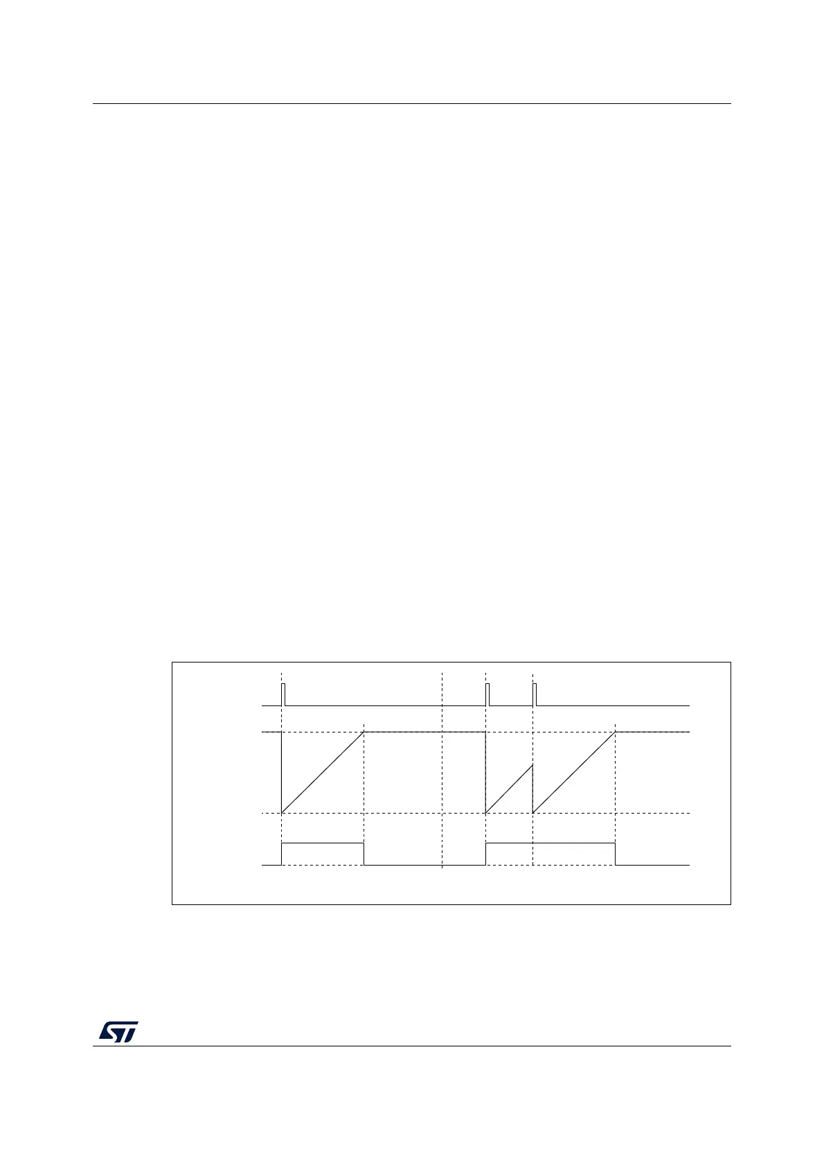
25.4.16 Retriggerable one pulse mode (TIM15 only)
This mode allows the counter to be started in response to a stimulus and to generate a
pulse with a programmable length, but with the following differences with Non-retriggerable
one pulse mode described in Section 25.4.15:
– The pulse starts as soon as the trigger occurs (no programmable delay)
– The pulse is extended if a new trigger occurs before the previous one is completed
The timer must be in Slave mode, with the bits SMS[3:0] = ‘1000’ (Combined Reset + trigger
mode) in the TIMx_SMCR register, and the OCxM[3:0] bits set to ‘1000’ or ‘1001’ for
Retrigerrable OPM mode 1 or 2.
If the timer is configured in Up-counting mode, the corresponding CCRx must be set to 0
(the ARR register sets the pulse length). If the timer is configured in Down-counting mode,
CCRx must be above or equal to ARR.
Note: The OCxM[3:0] and SMS[3:0] bit fields are split into two parts for compatibility reasons, the
most significant bit are not contiguous with the 3 least significant ones.
This mode must not be used with center-aligned PWM modes. It is mandatory to have
CMS[1:0] = 00 in TIMx_CR1.
Figure 265. Retriggerable one pulse mode
25.4.17 UIF bit remapping
The IUFREMAP bit in the TIMx_CR1 register forces a continuous copy of the Update
Interrupt Flag UIF into bit 31 of the timer counter register (TIMxCNT[31]). This allows both
TRGI
Counter
Output
MS33106V1

 Loading...


