Revision history RM0444
1382/1390 RM0444 Rev 5
42 Revision history
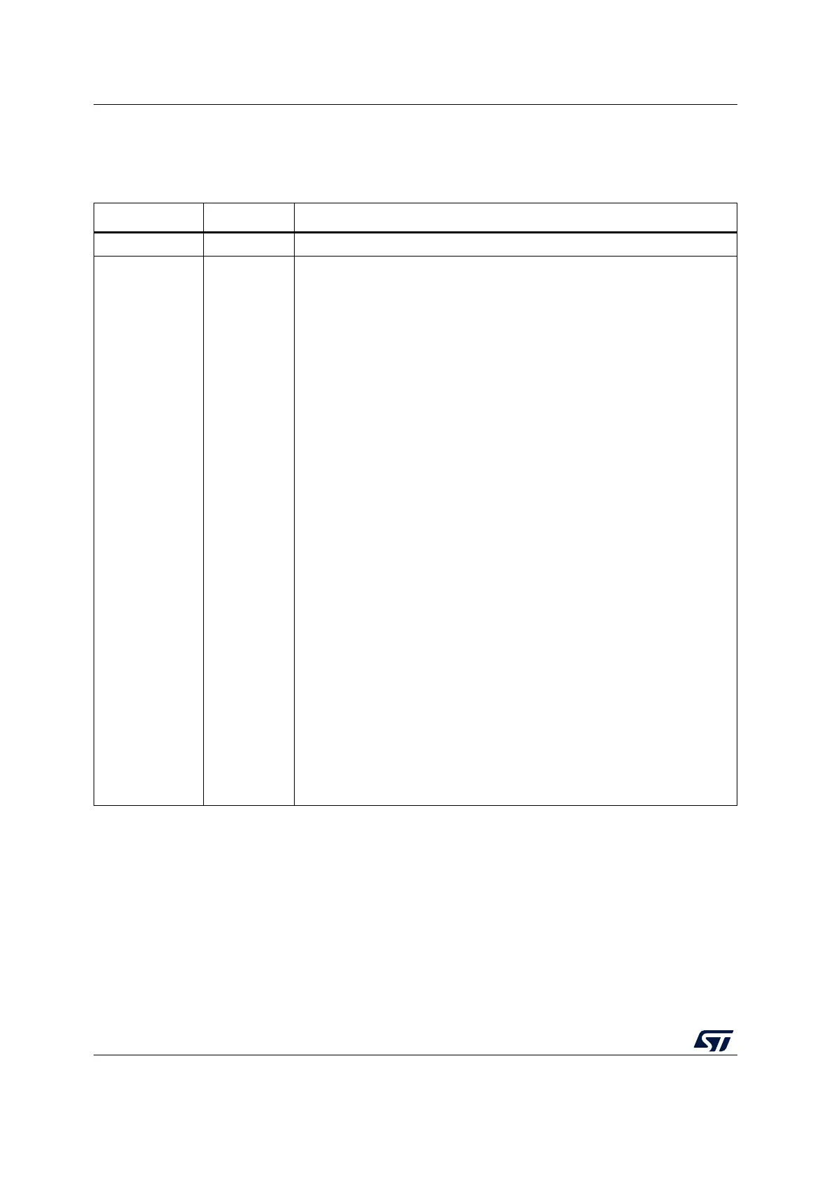
Table 256. Document revision history
Date Revision Changes
29-Oct-2018 1 Initial release.
17-Apr-2019 2
Integration of STM32G031xx and STM32G041xx, affecting:
– Section Availability of peripherals
– Figure Memory map
– Table STM32G031xx and STM32G041xx memory boundary addresses
(added)
– Section Embedded SRAM
– Section Boot configuration
– Section FLASH functional description
– Table Flash memory organization (title modified)
– Section Power control (PWR) (indication of bits not available on
STM32G031xx and STM32G041xx)
– Figure Clock tree
– Section Reset and clock control (RCC) (indication of bits not available on
STM32G031xx and STM32G041xx) and Section Timer clock
– Section System configuration controller (SYSCFG) (indication of bits not
available on STM32G031xx and STM32G041xx)
– Section SYSCFG configuration register 2 (SYSCFG_CFGR2) (clamping
diode enable bits added)
– Section Introduction
– Table DMA implementation
– Table DMAMUX instantiation
– Section Interrupt and exception vectors
– Section Extended interrupt and event controller (EXTI) (indication of bits not
available on STM32G031xx and STM32G041xx)
– Figure General-purpose timer block diagram and Figure External trigger
input block
– Section Infrared interface (IRTIM)
– Table USART features
– Table DEV_ID and REV_ID field values
– Table DBG APB freeze register 2 (DBG_APB_FZ2)
– Section
Package data register

 Loading...


