DocID024597 Rev 3 1025/1693
RM0351 Low-power timer (LPTIM)
1045
Programming the CKSEL and COUNTMODE bits allows controlling whether the LPTIM will
use an external clock source or an internal one.
When configured to use an external clock source, the CKPOL bits are used to select the
external clock signal active edge. If both edges are configured to be active ones, an internal
clock signal should also be provided (first configuration). In this case, the internal clock
signal frequency should be at least four time higher than the external clock signal frequency.
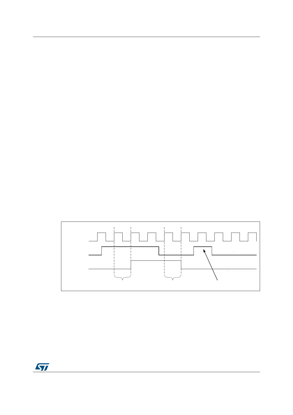
30.4.3 Glitch filter
The LPTIM inputs, either external or internal, are protected with digital filters that prevent
any glitches and noise perturbations to propagate inside the LPTIM. This is in order to
prevent spurious counts or triggers.
Before activating the digital filters, an internal clock source should first be provided to the
LPTIM. This is necessary to guarantee the proper operation of the filters.
The digital filters are divided into two groups:
• The first group of digital filters protects the LPTIM external inputs. The digital filters
sensitivity is controlled by the CKFLT bits
• The second group of digital filters protects the LPTIM internal trigger inputs. The digital
filters sensitivity is controlled by the TRGFLT bits.
Note: The digital filters sensitivity is controlled by groups. It is not possible to configure each digital
filter sensitivity separately inside the same group.
The filter sensitivity acts on the number of consecutive equal samples that should be
detected on one of the LPTIM inputs to consider a signal level change as a valid transition.
Figure 341 shows an example of glitch filter behavior in case of a 2 consecutive samples
programmed.
Figure 341. Glitch filter timing diagram
Note: In case no internal clock signal is provided, the digital filter must be deactivated by setting
the CKFLT and TRGFLT bits to ‘0’. In that case, an external analog filter may be used to
protect the LPTIM external inputs against glitches.
069
&/.08;
,QSXW
)LOWHURXW
FRQVHFXWLYHVDPSOHV FRQVHFXWLYHVDPSOHV )LOWHUHG

 Loading...


