DocID024597 Rev 3 287/1693
RM0351 Peripherals interconnect matrix
294
9.3 Interconnection details
9.3.1 From timer (TIM1/TIM2/TIM3/TIM4/TIM5/TIM8/TIM15/TIM16/TIM17) to
timer (TIM1/TIM2/TIM3/TIM4/TIM5/TIM8/TIM15)
Purpose
Some of the TIMx timers are linked together internally for timer synchronization or chaining.
When one timer is configured in Master Mode, it can reset, start, stop or clock the counter of
another timer configured in Slave Mode.
A description of the feature is provided in: Section 27.3.19: Timer synchronization.
VREFINT - - - - - - - - - - - - - 12 - - - - - - - - - - -
OPAMP1
- - - - - - - - - - - - - 12 12 - - - - - - - - - -
OPAMP2
- - - - - - - - - - - - - 12 12 - - - - - - - - - -
DAC1
- - - - - - - - - - - - - - 12 12 - 12 12 - - - - - -
DAC2
- - - - - - - - - - - - - - 12 12 - - - - - - - - -
HSE
- - - - - - - - - - 7 - - - - - - - - - - - - - -
LSE
- - 7 - - - - - 77- - - - - - - - - - - - - - -
MSI
- - - - - - - - - - 7 - - - - - - - - - - - - - -
LSI
- - - - - - - - - 7 - - - - - - - - - - - - - - -
MCO
- - - - - - - - - - 7 - - - - - - - - - - - - - -
EXTI
- - - - - - - - - - - - - 2225- - 44 - - - -
RTC
- - - - - - - - - 7 - 88- - - - - - - - - - - -
COMP1 13 13 13 13
- - - - 13 13 13 8 8 - - - - - - - - - - - -
COMP2 13 13 13 13
- - - - 13 13 13 8 8 - - - - - - - - - - - -
SYST ERR 14 14
- - - - - - 14 14 14 - - - - - - - - - - - - - -
USB
- - 11 - - - - - - - - - - - - - - - - - - - - - -
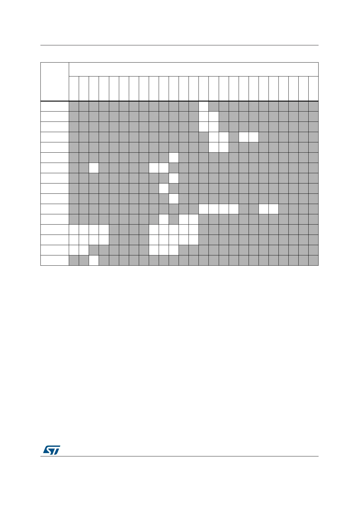
1. Numbers in table are links to corresponding detailed sub-section in Section 9.3: Interconnection details.
2. The “-” symbol in grayed cells means no interconnect.
Table 35. STM32L4x6 peripherals interconnect matrix
(1)
(2)
(continued)
Source
Destination
TIM1
TIM8
TIM2
TIM3
TIM4
TIM5
TIM6
TIM7
TIM15
TIM16
TIM17
LPTIM1
LPTIM2
ADC1
ADC2
ADC3
DFSDM
OPAMP1
OPAMP2
DAC1
DAC2
COMP1
COMP2
DMA
IRTIM