Liquid crystal display controller (LCD) RM0351
672/1693 DocID024597 Rev 3
In buffer mode, intermediate voltages are generated by the high value resistor bridge R
HN
to
reduce power consumption, the low value resistor bridge R
LN
is automatically disabled
whatever the HD bit or PON bits configuration.
Buffers can be used independently of the V
LCD
supply source (internal or external) but can
only be enabled or disabled when LCD controller is not activated.
After the LCDEN bit is activated, the RDY bit is set in the LCD_SR register to indicate that
voltage levels are stable and the LCD controller can start to work.
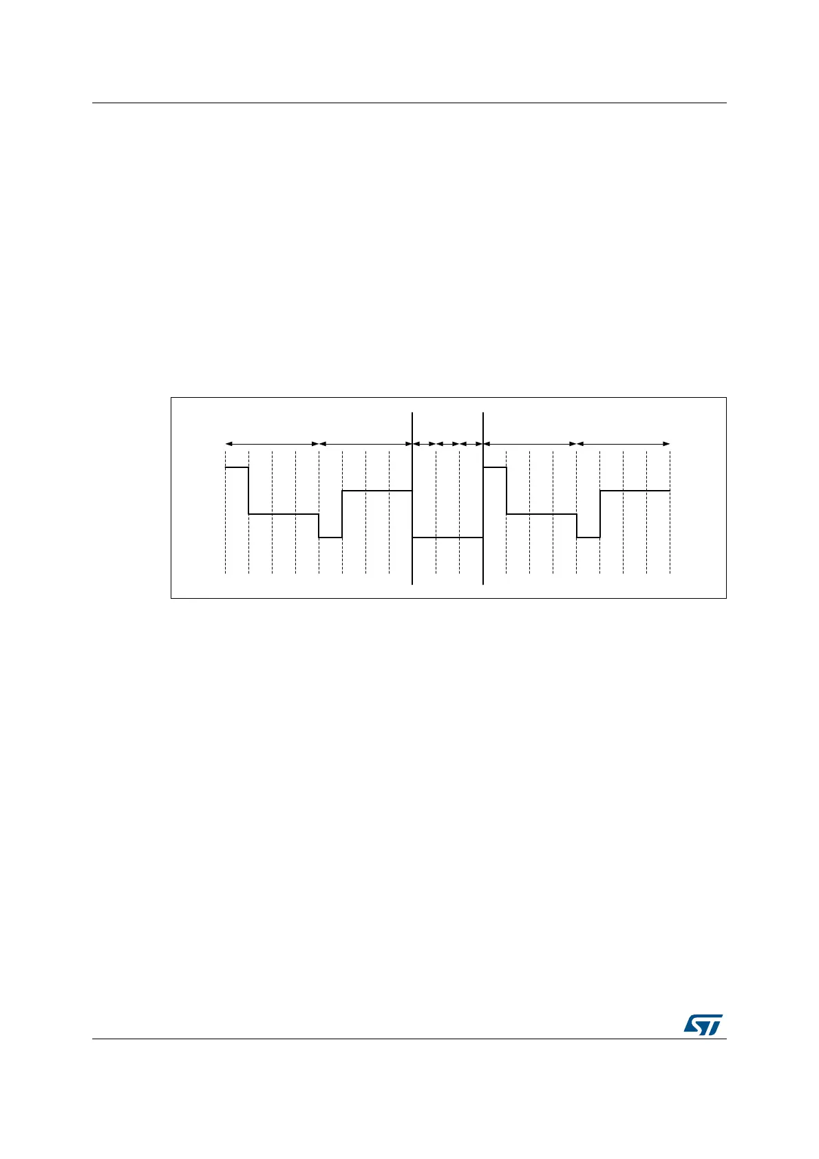
Deadtime
In addition to using the CC[2:0] bits, the contrast can be controlled by programming a dead
time between each frame. During the dead time the COM and SEG values are put to V
SS
.
The DEAD[2:0] bits in the LCD_FCR register can be used to program a time of up to eight
phase periods. This dead time reduces the contrast without modifying the frame rate.
Figure 162. Deadtime
069
ŽĚĚĨƌĂŵĞ ĞǀĞŶĨƌĂŵĞ ŽĚĚĨƌĂŵĞ ĞǀĞŶĨƌĂŵĞĚĞĂĚƚŝŵĞ