Universal synchronous asynchronous receiver transmitter (USART) RM0351
1180/1693 DocID024597 Rev 3
36.4 USART implementation
The STM32L4x6 devices embed 3 USARTs, 2 UARTs and 1 LPUART. The Table 191
describes the features supported by each peripheral.
36.5 USART functional description
Any USART bidirectional communication requires a minimum of two pins: Receive data In
(RX) and Transmit data Out (TX):
• RX: Receive data Input.
This is the serial data input. Oversampling techniques are used for data recovery by
discriminating between valid incoming data and noise.
• TX: Transmit data Output.
When the transmitter is disabled, the output pin returns to its I/O port configuration.
When the transmitter is enabled and nothing is to be transmitted, the TX pin is at high
level. In single-wire and Smartcard modes, this I/O is used to transmit and receive the
data.
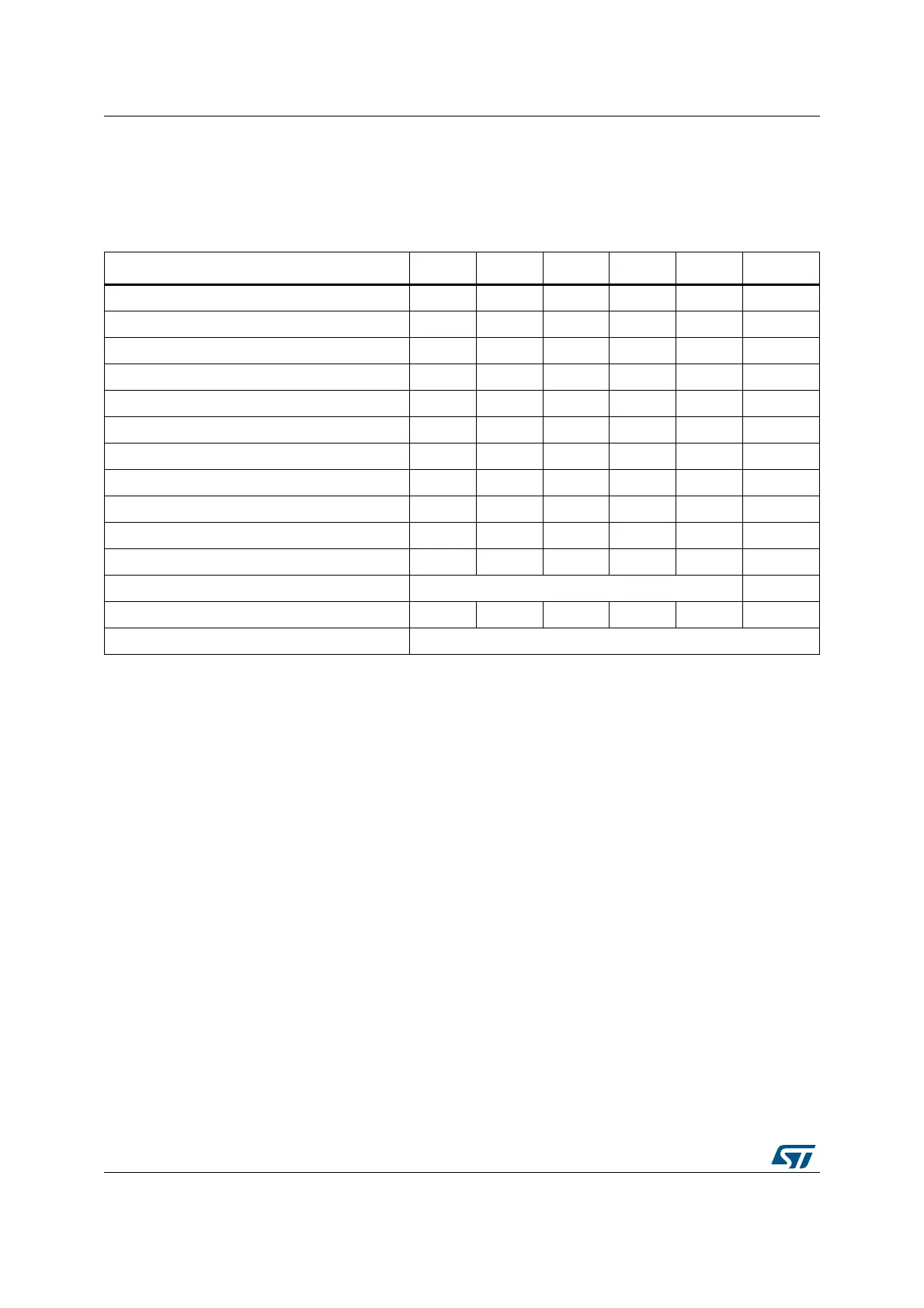
Table 191. STM32L4x6 USART/UART/LPUART features
USART modes/features
(1)
USART1 USART2 USART3 UART4 UART5 LPUART1
Hardware flow control for modem XXXXX X
Continuous communication using DMA XXXXX X
Multiprocessor communication XXXXX X
Synchronous mode X X X - - -
Smartcard mode X X X - - -
Single-wire half-duplex communication XXXXX X
IrDA SIR ENDEC block XXXXX -
LIN mode XXXXX -
Dual clock domain and wakeup from Stop modeXXXXX X
Receiver timeout interrupt XXXXX -
Modbus communication XXXXX -
Auto baud rate detection X (4 modes) -
Driver Enable XXXXX X
LPUART/USART data length 7, 8 and 9 bits
1. X = supported.

 Loading...


