DocID024597 Rev 3 483/1693
RM0351 Analog-to-digital converters (ADC)
540
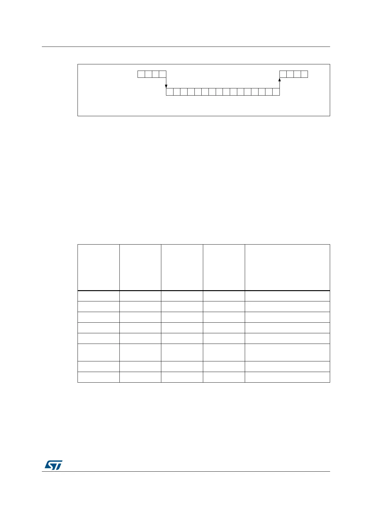
Figure 109. Oversampling in auto-injected mode
It is possible to have also the triggered mode enabled, using the TROVS bit. In this case, the
ADC must be configured as following: JAUTO = 1, DISCEN = 0, JDISCEN = 0, ROVSE = 1,
JOVSE = 1 and TROVSE = 1.
Dual ADC modes support when oversampling
It is possible to have oversampling enabled when working in dual ADC configuration, for the
injected simultaneous mode and regular simultaneous mode. In this case, the two ADCs
must be programmed with the very same settings (including oversampling).
All other dual ADC modes are not supported when either regular or injected oversampling is
enabled (ROVSE = 1 or JOVSE = 1).
Combined modes summary
The Tabl e 9 6 below summarizes all combinations, including modes not supported.
16.3.30 Dual ADC modes
In devices with two ADCs or more, dual ADC modes can be used (see Figure 110):
• ADC1 and ADC2 can be used together in dual mode (ADC1 is master)
In dual ADC mode the start of conversion is triggered alternately or simultaneously by the
ADCx master to the ADC slave, depending on the mode selected by the bits DUAL[4:0] in
the ADCx_CCR register.
Table 96. Oversampler operating modes summary
Regular Over-
sampling
ROVSE
Injected Over-
sampling
JOVSE
Oversampler
mode
ROVSM
0 = continued
1 = resumed
Triggered
Regular mode
TROVS
Comment
1 0 0 0 Regular continued mode
1 0 0 1 Not supported
1 0 1 0 Regular resumed mode
1 0 1 1 Triggered regular resumed mode
1 1 0 X Not supported
1110
Injected and regular resumed
mode
1 1 1 1 Not supported
0 1 X X Injected oversampling
069
5HJXODUFKDQQHOV 1
-$872 5296( -296( 52960 ;75296
1
1
1
,
,
,
,
-
-
-
-
.
.
.
.
/
/
/
/
1
1
1
1
,QMHFWHGFKDQQHOV

 Loading...


