Advanced-control timers (TIM1/TIM8) RM0351
842/1693 DocID024597 Rev 3
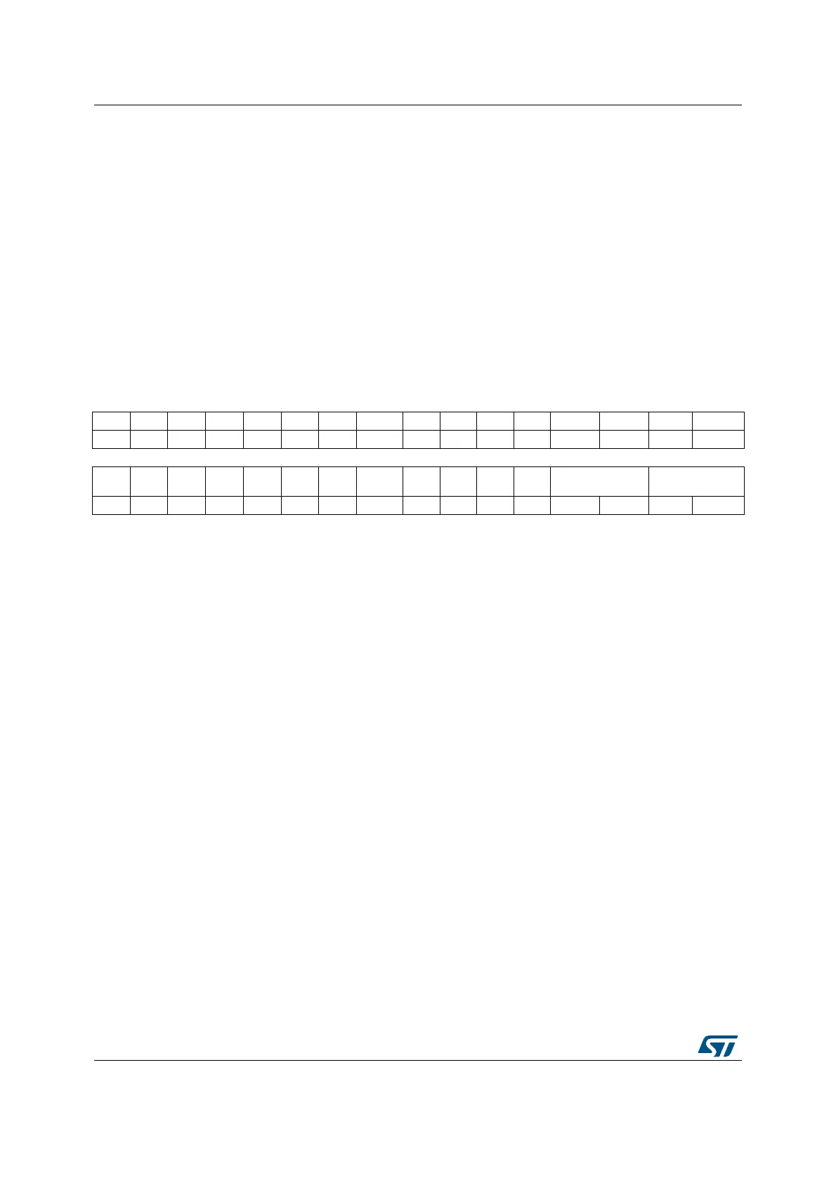
26.4.22 TIM8 option register 1 (TIM8_OR1)
Address offset: 0x50
Reset value: 0x0000 0000
Bits 1:0 ETR_ADC1_RMP: External trigger remap on ADC1 analog watchdog
00 : TIM1_ETR is not connected to ADC1 AWDx. This configuration must be selected when
the ETR comes from the I/O.
01 : TIM1_ETR is connected to ADC1 AWD1.
10 : TIM1_ETR is connected to ADC1 AWD2.
11 : TIM1_ETR is connected to ADC1 AWD3.
Note: ADC1 AWDx sources are ‘ORed’ with the TIM1_ETR input signals. When ADC1 AWDx
is used, it is necessary to make sure that the corresponding TIM1_ETR input pin is not
enabled in the alternate function controller. Refer to Figure 210: TIM1 ETR input
circuitry.
31 30 29 28 27 26 25 24 23 22 21 20 19 18 17 16
Res. Res. Res. Res. Res. Res. Res. Res. Res. Res. Res. Res. Res. Res. Res. Res.
1514131211109 8 7654 3 2 1 0
Res. Res. Res. Res. Res. Res. Res. Res. Res. Res. Res.
TI1_
RMP
ETR_ADC3_RMP ETR_ADC2_RMP
rw rw rw rw rw
Bits 31:5 Reserved, must be kept at reset value
Bit 4 TI1_RMP: Input Capture 1 remap
0: TIM8 input capture 1 is connected to I/O
1: TIM8 input capture 1 is connected to COMP2 output.
Bits 3:2 ETR_ADC3_RMP: External trigger remap on ADC3 analog watchdog
00: TIM8_ETR is not connected to ADC3 AWDx. This configuration must be selected when
the ETR comes from the I/O.
01: TIM8_ETR is connected to ADC3 AWD1.
10: TIM8_ETR is connected to ADC3 AWD2.
11: TIM8_ETR is connected to ADC3 AWD3.
Note: ADC3 AWDx sources are ‘ORed’ with the TIM8_ETR input signals. When ADC3 AWDx
is used, it is necessary to make sure that the corresponding TIM8_ETR input pin is not
enabled in the alternate function controller. Refer to Figure 211: TIM8 ETR input
circuitry.
Bits 1:0 ETR_ADC2_RMP: External trigger remap on ADC1 analog watchdog
00 : TIM8_ETR is not connected to ADC2 AWDx. This configuration must be selected when
the ETR comes from the I/O.
01 : TIM8_ETR is connected to ADC2 AWD1.
10 : TIM8_ETR is connected to ADC2 AWD2.
11 : TIM8_ETR is connected to ADC2 AWD3.
Note: ADC2 AWDx sources are ‘ORed’ with the TIM8_ETR input signals. When ADC2 AWDx
is used, it is necessary to make sure that the corresponding TIM8_ETR input pin is not
enabled in the alternate function controller. Refer to Figure 211: TIM8 ETR input
circuitry.

 Loading...