Touch sensing controller (TSC) RM0351
694/1693 DocID024597 Rev 3
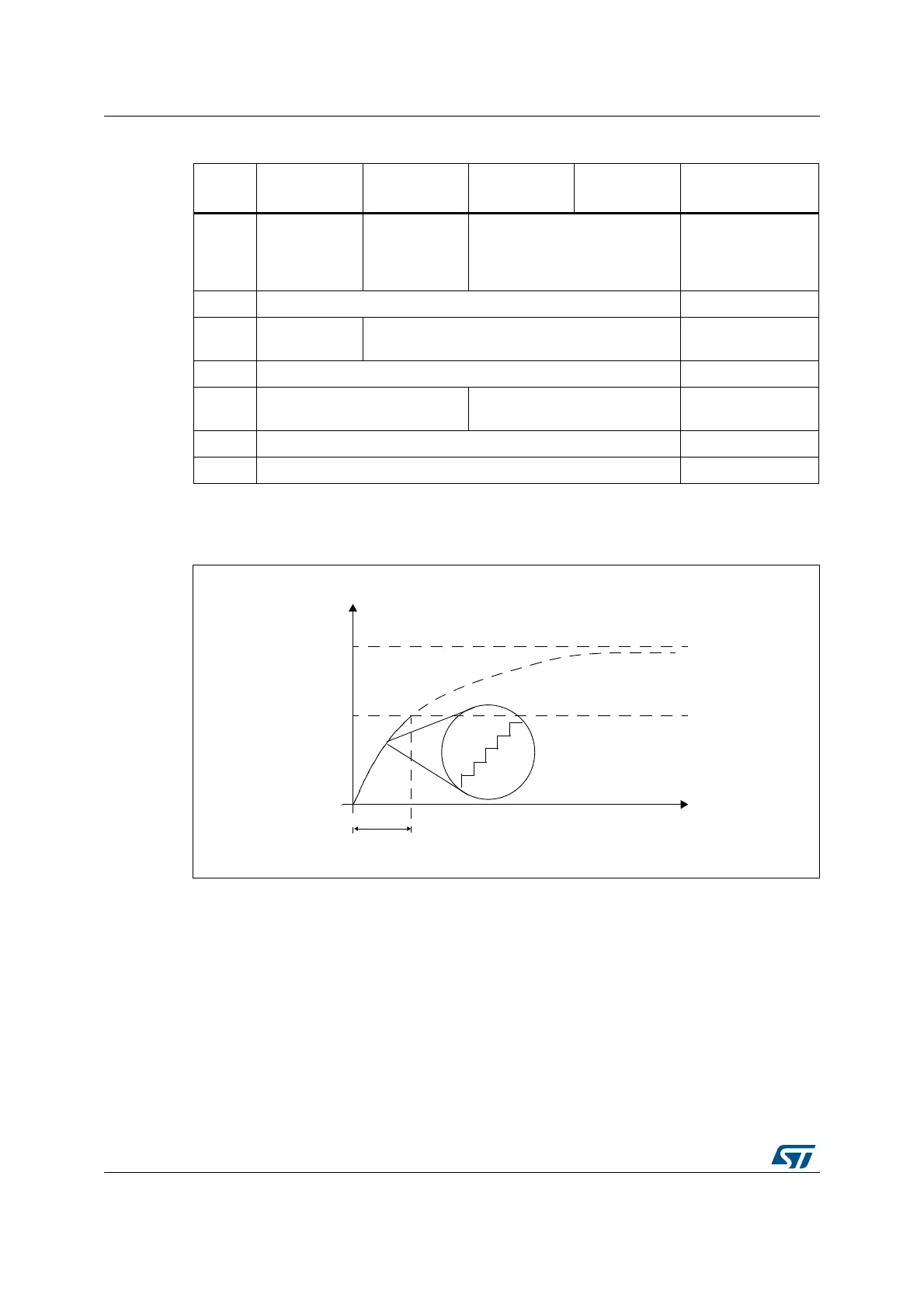
The voltage variation over the time on the sampling capacitor C
S
is detailed below:
Figure 167. Sampling capacitor voltage variation
23.3.3 Reset and clocks
The TSC clock source is the AHB clock (HCLK). Two programmable prescalers are used to
generate the pulse generator and the spread spectrum internal clocks:
• The pulse generator clock (PGCLK) is defined using the PGPSC[2:0] bits of the
TSC_CR register
• The spread spectrum clock (SSCLK) is defined using the SSPSC bit of the TSC_CR
register
The Reset and Clock Controller (RCC) provides dedicated bits to enable the touch sensing
controller clock and to reset this peripheral. For more information, please refer to Section 6:
Reset and clock control (RCC).
Table 134. Acquisition sequence summary
State
G1_IO1
(electrode)
G1_IO2
(sampling)
G1_IO3
(electrode)
G1_IO4
(electrode)
State description
#1
Input floating
with analog
switch closed
Output open-
drain low with
analog switch
closed
Input floating with analog switch
closed
Discharge all C
X
and
C
S
#2 Input floating Dead time
#3
Output push-
pull high
Input floating Charge C
X1
#4 Input floating Dead time
#5
Input floating with analog switch
closed
Input floating
Charge transfer from
C
X1
to C
S
#6 Input floating Dead time
#7 Input floating Measure C
S
voltage
-36
T
6
#3
4HRESHOLD6
)(
6
$$
"URSTDURATION

 Loading...


