DocID024597 Rev 3 1259/1693
RM0351 Low-power universal asynchronous receiver transmitter (LPUART)
1282
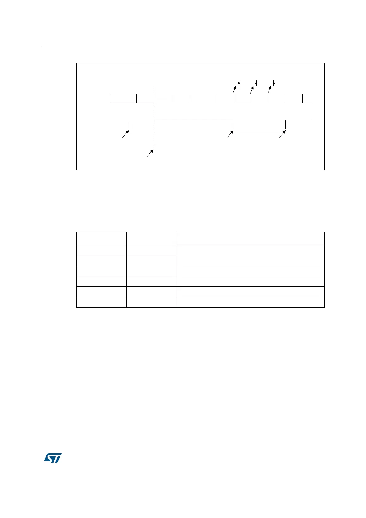
Figure 413. Mute mode using address mark detection
37.4.6 LPUART parity control
Parity control (generation of parity bit in transmission and parity checking in reception) can
be enabled by setting the PCE bit in the LPUART_CR1 register. Depending on the frame
length defined by the M bits, the possible LPUART frame formats are as listed in Table 196.
Even parity
The parity bit is calculated to obtain an even number of “1s” inside the frame which is made
of the 6, 7 or 8 LSB bits (depending on M bits values) and the parity bit.
As an example, if data=00110101, and 4 bits are set, then the parity bit will be 0 if even
parity is selected (PS bit in LPUART_CR1 = 0).
Odd parity
The parity bit is calculated to obtain an odd number of “1s” inside the frame made of the 6, 7
or 8 LSB bits (depending on M bits values) and the parity bit.
As an example, if data=00110101 and 4 bits set, then the parity bit will be 1 if odd parity is
selected (PS bit in LPUART_CR1 = 1).
06Y9
,'/( $GGU 'DWD 'DWD ,'/( $GGU 'DWD 'DWD $GGU 'DWD
,QWKLVH[DPSOHWKHFXUUHQWDGGUHVVRIWKHUHFHLYHULV
SURJUDPPHGLQWKH/38$57B&5UHJLVWHU
5;1(
1RQPDWFKLQJDGGUHVV0DWFKLQJDGGUHVV
1RQPDWFKLQJDGGUHVV
0054ZULWWHQWR
5;1(ZDVFOHDUHG
5:8
5;
0XWHPRGH 0XWHPRGH1RUPDOPRGH
5;1( 5;1(
Table 201. Frame formats
M bits PCE bit LPUART frame
(1)
1. Legends: SB: start bit, STB: stop bit, PB: parity bit.
2. In the data register, the PB is always taking the MSB position (9th, 8th or 7th, depending on the M bits
value).
00 0 | SB | 8-bit data | STB |
00 1 | SB | 7-bit data | PB | STB |
01 0 | SB | 9-bit data | STB |
01 1 | SB | 8-bit data | PB | STB |
10 0 | SB | 7-bit data | STB |
10 1 | SB | 6-bit data | PB | STB |

 Loading...


