DocID024597 Rev 3 1257/1693
RM0351 Low-power universal asynchronous receiver transmitter (LPUART)
1282
37.4.5 Multiprocessor communication using LPUART
It is possible to perform multiprocessor communication with the LPUART (with several
LPUARTs connected in a network). For instance one of the LPUARTs can be the master, its
TX output connected to the RX inputs of the other LPUARTs. The others are slaves, their
respective TX outputs are logically ANDed together and connected to the RX input of the
master.
In multiprocessor configurations it is often desirable that only the intended message
recipient should actively receive the full message contents, thus reducing redundant
LPUART service overhead for all non addressed receivers.
The non addressed devices may be placed in mute mode by means of the muting function.
In order to use the mute mode feature, the MME bit must be set in the LPUART_CR1
register.
In mute mode:
• None of the reception status bits can be set.
• All the receive interrupts are inhibited.
• The RWU bit in LPUART_ISR register is set to 1. RWU can be controlled automatically
by hardware or by software, through the MMRQ bit in the LPUART_RQR register,
under certain conditions.
The LPUART can enter or exit from mute mode using one of two methods, depending on
the WAKE bit in the LPUART_CR1 register:
• Idle Line detection if the WAKE bit is reset,
• Address Mark detection if the WAKE bit is set.
Idle line detection (WAKE=0)
The LPUART enters mute mode when the MMRQ bit is written to 1 and the RWU is
automatically set.
It wakes up when an Idle frame is detected. Then the RWU bit is cleared by hardware but
the IDLE bit is not set in the LPUART_ISR register. An example of mute mode behavior
using Idle line detection is given in Figure 390.
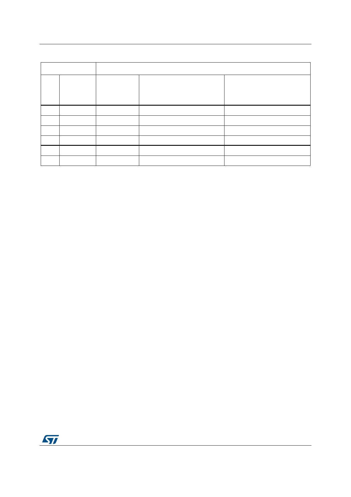
Table 200. Error calculation for programmed baudrates at f
ck
= 32,768 KHz
Baud rate f
CK
= 32,768 KHz
S.No Desired Actual
Value programmed in the baud
rate register
% Error = (Calculated - Desired)
B.rate / Desired B.rate
1 300 Bps 300 Bps 0x6D3A 0
2 600 Bps 600 Bps 0x369D 0
3 1200 Bps 1200.087 Bps 0x1B4E 0.007
4 2400 Bps 2400.17 Bps 0xDA7 0.007
5 4800 Bps 4801.72 Bps 0x6D3 0.035
6 9600 Bps 9608.94 Bps 0x369 0.093

 Loading...


