Serial audio interface (SAI) RM0351
1350/1693 DocID024597 Rev 3
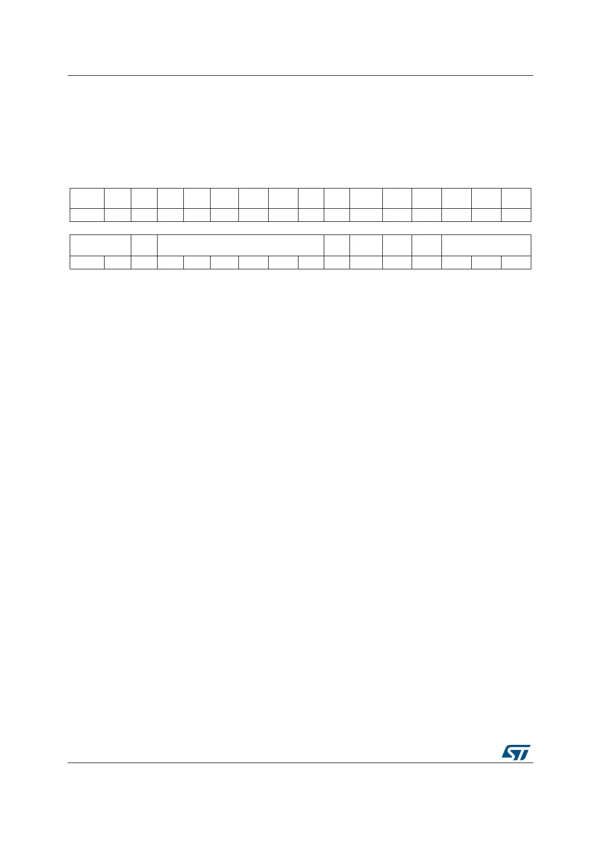
39.5.3 Configuration register 2 (SAI_ACR2 / SAI_BCR2)
Address offset: Block A: 0x008
Address offset: Block B: 0x028
Reset value: 0x0000 0000
31 30 29 28 27 26 25 24 23 22 21 20 19 18 17 16
Res. Res. Res. Res. Res. Res. Res. Res. Res. Res. Res. Res. Res. Res. Res. Res.
15 14 13 12 11 10 9 8 7 6 5 4 3 2 1 0
COMP[1:0] CPL MUTECNT[5:0]
MUTE
VAL
MUTE TRIS
FFLUS
H
FTH
rw rw rw rw rw rw rw rw rw rw rw rw w rw rw rw
Bits 31:16 Reserved, always read as 0
Bits 15:14 COMP[1:0]: Companding mode.
These bits are set and cleared by software. The µ-Law and the A-Law log are a part of the CCITT
G.711 recommendation, the type of complement that will be used depends on CPL bit.
The data expansion or data compression are determined by the state of bit MODE[0].
The data compression is applied if the audio block is configured as a transmitter.
The data expansion is automatically applied when the audio block is configured as a receiver.
Refer to Section : Companding mode for more details.
00: No companding algorithm
01: Reserved.
10: µ-Law algorithm
11: A-Law algorithm
Note: Companding mode is applicable only when TDM is selected.
Bit 13 CPL: Complement bit.
This bit is set and cleared by software.
It defines the type of complement to be used for companding mode
0: 1’s complement representation.
1: 2’s complement representation.
Note: This bit has effect only when the companding mode is µ-Law algorithm or A-Law algorithm.
Bits 12:7 MUTECNT[5:0]: Mute counter.
These bits are set and cleared by software. They are used only in reception mode.
The value set in these bits is compared to the number of consecutive mute frames detected in
reception. When the number of mute frames is equal to this value, the flag MUTEDET will be set and
an interrupt will be generated if bit MUTEDETIE is set.
Refer to Section : Mute mode for more details.

 Loading...


