General-purpose timers (TIM2/TIM3/TIM4/TIM5) RM0351
890/1693 DocID024597 Rev 3
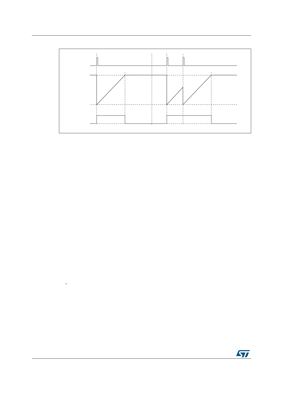
Figure 285. Retriggerable one pulse mode
27.3.15 Encoder interface mode
To select Encoder Interface mode write SMS=‘001 in the TIMx_SMCR register if the counter
is counting on TI2 edges only, SMS=010 if it is counting on TI1 edges only and SMS=011 if
it is counting on both TI1 and TI2 edges.
Select the TI1 and TI2 polarity by programming the CC1P and CC2P bits in the TIMx_CCER
register. CC1NP and CC2NP must be kept cleared. When needed, you can program the
input filter as well. CC1NP and CC2NP must be kept low.
The two inputs TI1 and TI2 are used to interface to an incremental encoder. Refer to
Table 152. The counter is clocked by each valid transition on TI1FP1 or TI2FP2 (TI1 and TI2
after input filter and polarity selection, TI1FP1=TI1 if not filtered and not inverted,
TI2FP2=TI2 if not filtered and not inverted) assuming that it is enabled (CEN bit in
TIMx_CR1 register written to ‘1). The sequence of transitions of the two inputs is evaluated
and generates count pulses as well as the direction signal. Depending on the sequence the
counter counts up or down, the DIR bit in the TIMx_CR1 register is modified by hardware
accordingly. The DIR bit is calculated at each transition on any input (TI1 or TI2), whatever
the counter is counting on TI1 only, TI2 only or both TI1 and TI2.
Encoder interface mode acts simply as an external clock with direction selection. This
means that the counter just counts continuously between 0 and the auto-reload value in the
TIMx_ARR register (0 to ARR or ARR down to 0 depending on the direction). So you must
configure TIMx_ARR before starting. In the same way, the capture, compare, prescaler,
trigger output features continue to work as normal.
In this mode, the counter is modified automatically following the speed and the direction of
the
quadrature encoder and its content, therefore, always represents the encoder’s position.
The count direction correspond to the rotation direction of the connected sensor. The table
summarizes the possible combinations, assuming TI1 and TI2 don’t switch at the same
time.

 Loading...


