Analog-to-digital converters (ADC) RM0351
528/1693 DocID024597 Rev 3
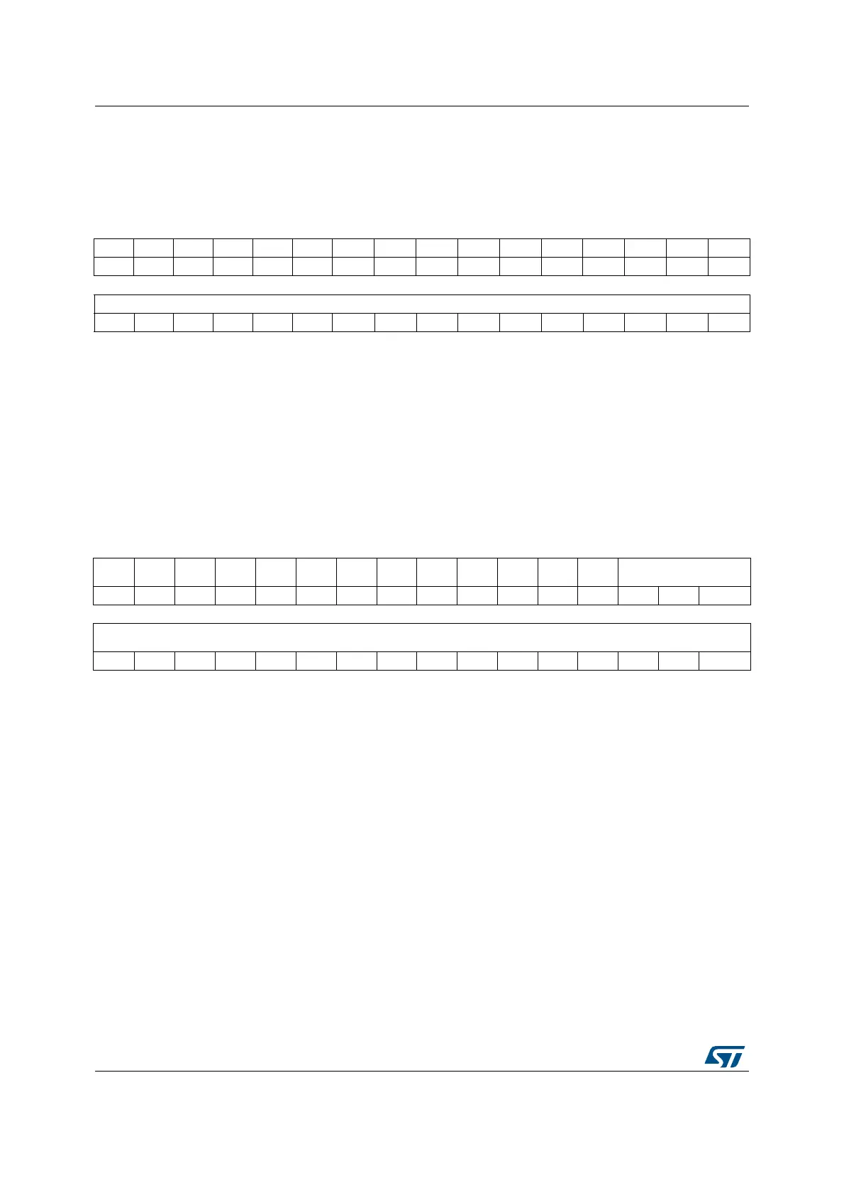
16.5.18 ADC injected data register (ADCx_JDRy, y= 1..4)
Address offset: 0x80 - 0x8C
Reset value: 0x0000 0000
16.5.19 ADC Analog Watchdog 2 Configuration Register (ADCx_AWD2CR)
Address offset: 0xA0
Reset value: 0x0000 0000
31 30 29 28 27 26 25 24 23 22 21 20 19 18 17 16
Res. Res. Res. Res. Res. Res. Res. Res. Res. Res. Res. Res. Res. Res. Res. Res.
1514131211109876543210
JDATA[15:0]
rrrrrr r r r r rrrrrr
Bits 31:16 Reserved, must be kept at reset value.
Bits 15:0 JDATA[15:0]: Injected data
These bits are read-only. They contain the conversion result from injected channel y. The
data are left -or right-aligned as described in Section 16.3.26: Data management.
31 30 29 28 27 26 25 24 23 22 21 20 19 18 17 16
Res. Res. Res. Res. Res. Res. Res. Res. Res. Res. Res. Res. Res. AWD2CH[18:16]
rw rw rw
151413121110987654321 0
AWD2CH[15:0]
rw rw rw rw rw rw rw rw rw rw rw rw rw rw rw rw
Bits 31:19 Reserved, must be kept at reset value.
Bits 18:0 AWD2CH[18:0]: Analog watchdog 2 channel selection
These bits are set and cleared by software. They enable and select the input channels to be guarded
by the analog watchdog 2.
AWD2CH[i] = 0: ADC analog input channel-i is not monitored by AWD2
AWD2CH[i] = 1: ADC analog input channel-i is monitored by AWD2
When AWD2CH[18:0] = 000..0, the analog Watchdog 2 is disabled
Note: The channels selected by AWD2CH must be also selected into the SQRi or JSQRi registers.
Software is allowed to write these bits only when ADSTART=0 and JADSTART=0 (which
ensures that no conversion is ongoing).